Continue to Site

Eng-Tips is the largest engineering community on the Internet

Intelligent Work Forums for Engineering Professionals

  • Congratulations The Obturator on being selected by the Eng-Tips community for having the most helpful posts in the forums last week. Way to Go!

Slotted Counterbore

DougTheThug

Student
Jan 15, 2025
7
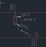
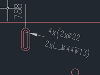
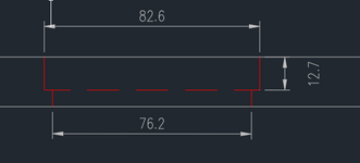
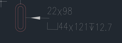
Does anyone know if there is a correct way to denote a slotted counterbore? I've made these drawings based on what I think is the correct notation for slots and counterbore. I also added a cross section of what I'm trying to convey. Don't mind my rounding. I know I should just use the cross section but I want to get peoples thoughts on the views without the cross section. Thanks.

Edit: Should clarify that the 4x is to indicate that there are 4 of these slots. I have noted the full length and width on a different slot so that the drawing doesn't get too busy in one place.
 

Attachments

  • 1736955021626.png
    1736955021626.png
    26.6 KB · Views: 8
  • 1736955181763.png
    1736955181763.png
    18.6 KB · Views: 8
  • 1736955389218.png
    1736955389218.png
    11.9 KB · Views: 8
Last edited:
Replies continue below

Recommended for you

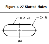
A typical slot is full width X full length and an indication of 2XR to indicate a full radius (not necessary to use "FULL") for ASME Y14.5.
 
A typical slot is full width X full length and an indication of 2XR to indicate a full radius (not necessary to use "FULL") for ASME Y14.5.
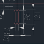
So I've done this on a separate slot already (ignore how messy it is) but how do I indicate the counterbore information? I was trying to work it into the 2XR as I don't see how else to include it in a clean way.
 

Attachments

  • 1736965416559.png
    1736965416559.png
    34.8 KB · Views: 2
You can do 44 X 121 (depthsymbol) depth dimension with a leader to the slot outline. If this is Creo then create a note with a leader and use the width and length and depth dimensions in the note to keep it parametric. The "2X R" is a separate note with a leader; it should be an allowable modifier to be radial, but that's not required.

This is from ASME Y14.5-2018:

slot2.PNG
 
You can do 44 X 121 (depthsymbol) depth dimension with a leader to the slot outline. If this is Creo then create a note with a leader and use the width and length and depth dimensions in the note to keep it parametric. The "2X R" is a separate note with a leader; it should be an allowable modifier to be radial, but that's not required.

This is from ASME Y14.5-2018:

View attachment 3571
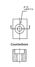
Do you think this note would make sense? I'm using the counterbore format for a hole but swapping radii with slot dimensions. The smaller part of the slot being the upper dimension and the counterbore being the bottom dimension. Would this be clear on an engineering drawing? Thanks for the help.
 

Attachments

  • 1737034479780.png
    1737034479780.png
    37.9 KB · Views: 9
  • 1737034656153.png
    1737034656153.png
    13.1 KB · Views: 8
Give it a try. At the worst you will end up with a section through the slot to put the depth dimension on because someone will be all put out.
 
Remove the diameter references. There is no full diameter and that is not what is being dimensioned, the width is. This is why the standard shows the R callout separately.
 
Give it a try. At the worst you will end up with a section through the slot to put the depth dimension on because someone will be all put out.
A section view will also explicitly define which side the cut out is facing.
So, when (not if) the mistake is made by production, you can point at the section view and show it to your boss.
 

Part and Inventory Search

Sponsor