Eng-Tips is the largest engineering community on the Internet

Intelligent Work Forums for Engineering Professionals

Soil movement due to open cut excavation 1

Status
Not open for further replies.

dss975599

Civil/Environmental
Dec 31, 2021
5
0
0
SG
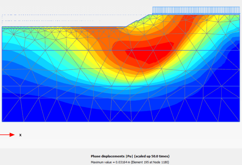
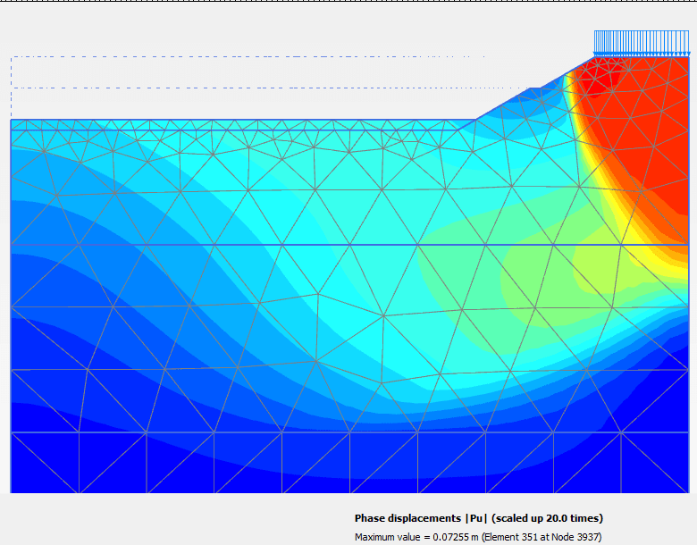
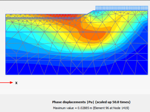
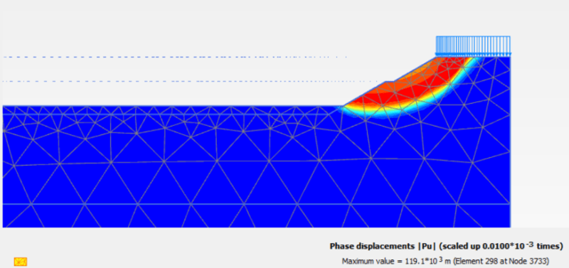
When I model an open up excavation in the computer model , I found that when the surcharge applied on slope is long enough , the soil movement (downwards under the surcharge region) is lower , when I model the short region of surcharge, I found that the soil movement underneath the region of surcharge is higher.

I just don't understand this situation , can someone help to explain it?

The top region is soft clay, excavation happens in soft clay, underlain is hard layer of soil.

0028_r0br4l.png


0029_fbyrsk.png
 
Replies continue below

Recommended for you

I also found that when the region of surcharge applied is short, the slip circle shown is like toe circle, when the region of surcharge applied is long, the slip circle is like base failure. How does the slip circle failure mode relate to the movement of soil ?
 
Interesting question.
Is it the same model (exactly), except with different loads? Or are you comparing two different model geometries with different loads?
Also, just from a comparison of the graphics above, one of the loadings near the top hinge has an offset, the other one does not. Appears minor, but worth asking.
From the graphics, you are using Plaxis 2D. Make sure that your phased analysis is exactly the same, starting with Ko.
More importantly, if one of the analysis steps (phases) is a safety analysis, the displacements are not meaningful as they tend to be orders of magnitude above elastic-plastic displacements. Plaxis tells you this in their manuals.
 

Thanks for your reply. I am still new to Plaxis. Yes, they are the same model with same loading but different geometry, it appears that the displacement of soil is higher when the applied surcharge is shorter . The results posted earlier weren't FOS phase, they are the results for final excavation stages(same phases for both) . Let's assume the effect of loading offset to be negligible at this juncture. Does it make sense ?

I have been figuring out which part went wrong for the whole day, but still couldn't figure out which part goes wrong.
 
Is the boundary conditions the same on both models?

They should be free to move in Z axis on both models.

TBH I don’t think its the issue but something is up with your second model. Your line load extends right up to the model boundary but yet there is no displacement beneath the load which can not be possible.

Are you sure the line load is activated in the last stage? Or is there no load applied or something?

]

And as a general rule, your model should be sufficiently large so that you have no displacement at the boundaries. If your models are too small you will get more settlement as there is nothing providing support to the soil at the boundaries.
 
Take a 2nd look at your displacements. Orders of magnitude different. That should give you a clue - you can't compare the two runs.
 

Updated with the correct diagram. The soil displacement with longer surcharge is lower, why ? shouldn't the longer the surcharge , the more critical it is ? Hence, the higher the soil displacement is ?
1_yfnx3o.png


2_m2cfug.png
 
Your second model is showing max displacement at the boundary, which makes sense to me. I would have thought settlement at the right boundary of your top model would also be higher but at least its giving some settlement. Good that you fixed this in your second model. Its very hard to troubleshoot a model without going through it in Plaxis.

Extend both models by another 20m to the right, but dont extend the line load. Also run a c-phi reduction analysis and lets see what your failure plane looks like.

And your mesh is too coarse, this could be affecting your results. Use a fine mesh.
 
EireChch said:
Extend both models by another 20m to the right, but dont extend the line load
EireChch said:
And your mesh is too coarse, this could be affecting your results. Use a fine mesh.

Great feedback on modelling. you don't see these type of commentary in the manuals and tutorials which tell you make a model and assign a mesh and not understanding how for the model needs to extend and how tight the mesh needs to be and where.

 
I do not do soil modelling... but perhaps the strains for the longer surcharge may be more likely 1-D strains (vertical direction) while for the shorter surcharge, the strains may be more likely 3-D strains. The shorter surcharge acts like a footing. I also agree with EireChch - the extent of the analysis shall be larger to the right to create a "half space" model (create a space big enough so the results will not be affected).
 
Status
Not open for further replies.
Back
Top