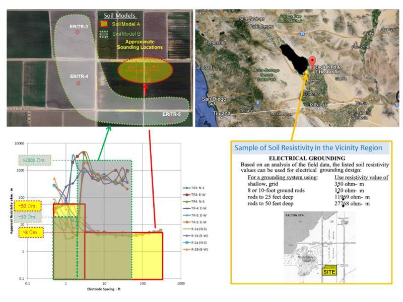
Eng-Tips is the largest engineering community on the Internet

Intelligent Work Forums for Engineering Professionals

soil resistivity measurement and interpertation

Status
Not open for further replies.
Replies continue below

Recommended for you

I don't know what you mean by the measurements not being good but if you are trying to create a two or three layer model for the whole thing or something for each section I would just pick the layers to be something conservative and move on.
 
The measured apparent resistance should decrease with increasing the electrode spacing, we do not see this trend up to almost 7 feet.
 
Sometimes the soil at deeper levels is higher resistivity than at shallow levels. You could have an upper layer of moist soil and high resistivity bedrock at a lower level. It depends on the nature of the soil. Resistivity measurements can also be influenced by metallic objects in the soil near the measurements, such as fences, distribution line grounds, water pipes, etc.
 
That is correct for this reason we are interested in soil resistivity of the entire site without impact of any metallic objects as you named during the measurements. The given measurements data are not a good representation for coming up with a soil model.
 
I think jghrist has it right.

The photo indicates this is some sort of rural area.

Are any water well records available for wells in the area?

Where I am our State Dept. of Natural Resources has put all well records, dating back decades, on line.

(They were always available the old-fashioned way, but it is much easier now.)

I have used these to gain insight into the soil characteristics in a couple of locations where we built substations.

These records should show the type(s) of soil encountered, whether or not there is bedrock, and the water table level.

If this is not available you could consider hiring a geo-technical consultant to bring his rig to the site and drill a few boreholes, as is normally done for foundation design.

Also, you may want to probe deeper using even wider electrode spacing, it appears that resistivity may be trending lower at deeper levels.

In that case some deep well type electrodes may be helpful to lower overall ground grid earth resistance.
 
I agree with MKFPE - have any geotechnical boreholes been drilled/test pits dug in the area/etc for design of the overall project? I have found this type of data can help interpret soil resistivity measurements for grounding design, if available.

For what it's worth, your apparent resistivity vs probe spacing measurements for most of your traverses are pretty consistent in terms of the curve shape. Your measurements look to me like there may be a very high resistivity layer pretty close to the surface.

Also keep in mind for shorter probe spacing on your Wenner measurements, you will likely have to correct the measured results based on the probe depth as the spheres of influence of your electrodes will overlap. Depth of your probes should be less than 0.05-0.10 x your probe spacing, which can be difficult to achieve in practice on short spacing measurements. This may not be the cause of your perceived issue, however is easy to overlook.
 
Taha234, although many soil resistivity decrease with the depth, I am not sure how accurate is your statement but definitely is not a universal rule. There are soil resistivity structures that behave completely different to what you state above (see the enclosed link for reference).
[sub][/sub]

Soil Test comparison: The tests 3, 4 & 5 are consistently shown low resistivity on the top layer and very high resistance in the lower layer. Tests 1 & 2 are also consistent however, in conflict with the other tests performed in the vicinity.

Are the tests wrong? Not necessarily. In rocky or large layers of sandy soil structure, the lower layer could be of high resistance as shown in the data. It is not unusual in valleys of the West coast with dry desert region near rocky mountain to have such as high diversity of soil in small area.

Suggestions: follow some of the recommendation above with the support of a geotech engineer and verify with additional test to confirm the result of the first test. If this is confirmed, the grounding design and calculation could be still performed using the appropriate information even if there is a high soil resistivity.

For illustration, see the picture below. Good luck.
Soil_Resistivity_-_Two_Models_z6blzb.jpg
 
I have two more short measurements which are not close to Test 1 and 2 but closer to Test3 3, 4 and 5. These two measurements S1 and S2 are consistent with Tests 1 and 2. I have attaché the graph for Measured Apparent resistance in ohm not Apparent resistance(ohm-m). It seems that the soil structure for the area seems to be as follow:

Clay:

Top Stiff to very stiff
Middle: Soft to medium stiff clayey silt
Bottom: Medium dense to dense Silty sand
 
 http://files.engineering.com/getfile.aspx?folder=16e90864-f57d-4947-b9e9-30f249380bf1&file=Doc3.pdf
Any reason why the graph for TR3 to TR5 changed between files Doc1.pdf and Doc3.pdf?
Suggestions:
i) Use only the apparent (calculated) resistivity to avoid confusion.
ii) Apparent Resistivity (Rho) ~ 1.915*(probe Separation- A)*(Measured Resistance-R)
 
Taha223.

Consider the following data ranges:
1) Upper layer (above 3 ft) ................100 > ρ > 1.0 Ω.m ([sub]all measurements are consistent)[/sub]
2) Mid layer between 3 to 6 ft ...........1000 > ρ > 100 Ω.m [sub](large diversity measurement)[/sub]
3) Lower layer between 6 ft to infinite.... 100 > ρ > 5 Ω.m for TR cases and
.................................................................. 1 > ρ > 0.01 Ω.m for the R and S cases

Suggested practical though:
The ground grids could be located 24 in below grade in the upper layer 100 and 1.0 Ω.m and ground rods could be used to bypass the mid layer and reach the lower layer at 10 ft. below grade (100 & 5 Ω.m or less). Therefore, the uncertainties on the mid layer measurement could have minimum impact in the overall ground grid design.
[sub]Noted that the low resistivity is associated with aggressive soil corrosivity that need to be considered in the size of the grid conductor and foundations rebar[/sub]

Good luck

 
Status
Not open for further replies.
Back
Top