Eng-Tips is the largest engineering community on the Internet

Intelligent Work Forums for Engineering Professionals

SOL 701 - Problematic Behaviour of Ruptured Elements

Status
Not open for further replies.

jacksonfem

Structural
Dec 8, 2010
52
0
0
GR
I tried many to times to run an Explicit analysis, but I think Femap doesn 't behave as it should, or better, as other Explicit solvers do. Like LS-Dyna or Abaqus.
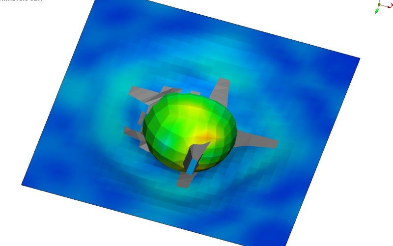
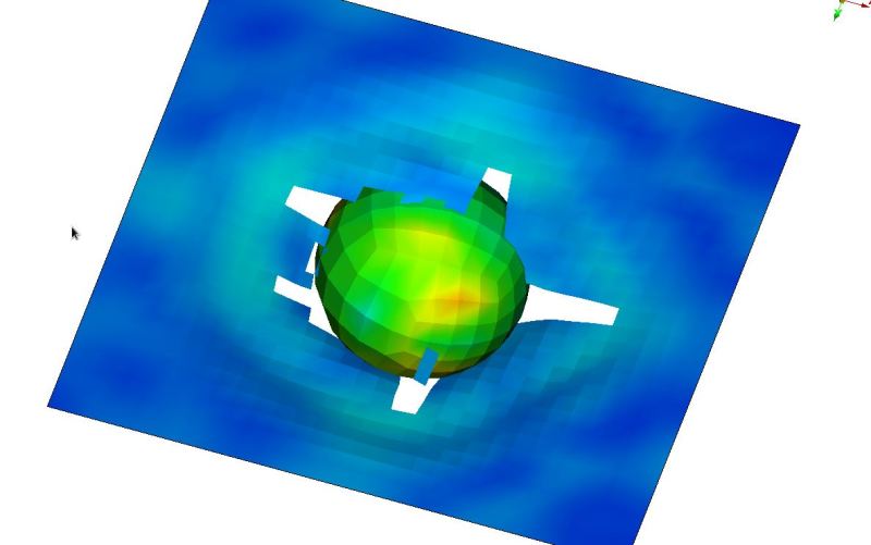
I tried to do something like this (select the animated result to see it better).

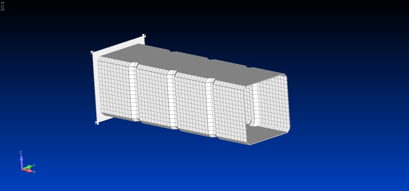
The LS-Dyna material of the tube is the well-known MAT_024 Piecewise Linear Plasticity. I made a stress-strain curve according to the example, also considering the "rupture" element flag in SOL 701 and the corresponding fail strain.

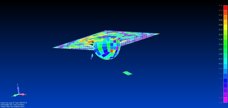
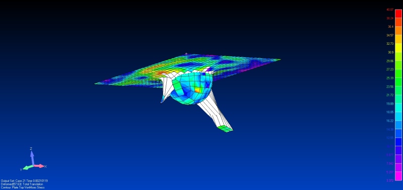
The problem is that when the elements fail, there are HUGE strains and displacements. The elements should not appear anymore, as with all Explicit solvers. I cannot understand why Femap present fail elements like this. It 's very annoying.

1_dnxxnd.jpg


2_yrsemy.jpg


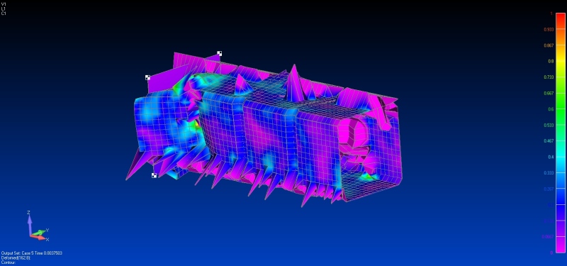
You can also see it on other models...

3_tahj5g.jpg


4_jw4vkn.jpg


Can anyone give me a help on this problem?

Thanks!
 
Replies continue below

Recommended for you

Also, in this video the same happens, but the user did the "trick" with the black backround and the black elements color and the problem is not well appearing.
Also, in the 3rd video here you can see the strange white elements beside the bullet. By the way, the 4th video where it seems right, it seems that something 's going wrong with the Femap interface...that "TIME" up-left, definitely is not a femap feature. Maybe it 's not with NxNastran...
 

Hi jacksonfem,

I'm not an expert but the wired element shape from secend picture in your post happened to me before. Usually the reason was too coarse mesh. With smaller elements it was fixed. Have you tried this already?
 
I have tried also with smaller elements to other models, and I always had the same problem.
I have analyzed models with bigger elements on other explicit solvers, such as Ls-Dyna and Pam-Crash and never had such problems.
Only with NxNastran I have this annoying problems...
 
The problem is that Femap does not have the opportunity for not showing the failed elements.
Below you can see the above file with the ball and plate, reading from another post-processor, not Femap.
In the first picture you can see the failed elements as it came from Femap, with grey color.
In the next picture the failed elements are not shown and the model is pretty nice!!
1_wrlwad.jpg
2_ibmybx.jpg
 
Hi
I think you should take a look at View Options - Criteria Levels and "Elements that pass" vs "Elements that fail". Femap does have the functionality for not showing failed elements. I have used it but it was a while back so I don't remember directly how I did it.

Good Luck

Thomas
 
Criteria levels for elements that Pass or Fail has nothing to do with the visibility of the failed elements in contour style view results. Are for criteria style view results. But even if I turn the results presentation to criteria view, these parameters does not affect the view of failed elements.

If you search the web for Implicit/Explicit analysis with sols 601/701 with Femap, including ruptured elements, you can see that always the background, elements and element edges are black or white. With this way the results are presented better than with the default view colors.
I think that it 's something very simple that Femap must have.
 
UPDATE!

I only made it with criteria style. I set up right the criteria levels for pass and fail and it works fine. The failed elements are not showed. But in contour style the problem remains....

5_hc4cgi.jpg
6_dndbp6.jpg
 
Hi again
Well it has nothing to do with Criteria Levels, like you say, but instead it is Criteria Limits that should be used. I kney it was something with the criteria settings.

So Femap can do it, in Criteria Style mode.

Thomas
 
Status
Not open for further replies.
Back
Top