Continue to Site

Eng-Tips is the largest engineering community on the Internet

Intelligent Work Forums for Engineering Professionals

  • Congratulations KootK on being selected by the Eng-Tips community for having the most helpful posts in the forums last week. Way to Go!

Solar Panels on roof's do they actually bother checking before Installing? 2

Status
Not open for further replies.

Alistair_Heaton

Mechanical
Nov 4, 2018
9,441
I have already 39 panels on my roof and they come in at 110kg per m2.

Its a new roof and I did some quick and ruff calc's with a wind load of 25kg per m2, snow 85kg per m2, suction of 45kg per m2.

600mm spacing between trusses so pretty standard.

My roof comes in at 1.6 safety factor. So I didn't bother saying anything.

Now just went round to a house with a roof with 1000mm spacing...… because they are thinking about getting them. Quiet why they have that spacing I have zero clue.

The solar installers are saying its good to go and no problems hand the cash over..…

To me they all come across as more Electrical inclined than Structural in the Solar game. And to be honest more fuse box whallah's than Electrical Engineers.

I will admit I have never done house roofs so have no real feel for what's a normal safety factor. But if mine comes in at 1.6 with 600mm spacing its a bit dodgy in my book with 1000mm.

Just wondering if anyone else has seen this throw them up without checking for solar panels.

Also wondering if the slot up the back of the rack and panels can turn the whole roof into a slated aerofoil.



Replies continue below

Recommended for you

Alistair. Do they worry about the starting PF or the running PF.
Ask the Kostal people about:
1. Capacitors on the AC motor.
2. Boosting the voltage on the inverter when the PF drops.
That's how we pick up VARs on a paralleled generator.
We use a cross compensation system that monitors the reactive current from both paralleled generators and tweaks the voltage set points so that the generators will share VARs properly.
Rather than a lot of gear to monitor the VARs you may be able to use a simple circuit that adds a predetermined bias to the voltage set point when the AC is running.
Ask Kostal.


Bill
--------------------
"Why not the best?"
Jimmy Carter
 
Inverters these days (well, at least the commercial size ones, not sure about residential) have the ability to maintain power factor at a specific location.
Indeed, there are now requirements for sites over a certain size here to specifically set inverters up to alter VAr output depending on system voltage, and they're also capable of power factor management in addition to real power output, although they're obviously still VA output devices.

EDMS Australia
 
The inverter can be set for between 0.9 either side. Mine is set at 1 and I can't change it as an owner. But it's a fixed output.


The grid contract has various levels of allowable power factor fluctuations. And the grid smart meter will cut you off if you exceed those limits.

Per say the pump is fine if it's the only thing coming online. But with the addition of an induction hob with 7.5 kW output, and the local female belief that pans heat quicker if you select max to start with. Education does not stop them. I can pull the PF quiet low. Luckily the heating controller has a locked out thermostat with a timed boost feature so they can't screw up the under floor heating. If you combine the two at the same time it gets near the 0.5s limit. Once the compressor is online it's fine. I stuck an extra fan coil on the cooling circuit so at 25 Deg house temp with a 20 degree target there is enough output that it's more than the heat pumps min cooling output. Which has stopped the short cycling. The heat pump companies solution was to stick a 500ltr buffer tank which wasn't an acceptable solution for me.


The grid guy wasn't bothered after he found out it wasn't due to some old Soviet community workshop gear being used. I suspect he changed the settings on the meter and increased the window up to 1 second. But would prefer to get it fixed properly.

All it needs to fix it is for the inverter to come off line in side 0.5 seconds and let the grid take the full load. Then come back online when it's back to running. The book of is 0.7 during start up I think. Then it's above 0.9 while running.

It was fine until I put the induction hob in.
 
Alistair said:
It was fine until I put the induction hob in.
Interpose a timer between the thermostat and the A/C.
When the thermostat demands cooling, drop out the induction hob for about 10 seconds while the A/C starts.
You may have to add a contactor to the hob.
Wiring:
The hob is energized by normally closed contacts.
When the thermostat energizes the relay, the contacts open, dropping out the hob.
A set of instantaneous contacts starts the A/C.
A set of normally open timed contacts re-energizes the hob about 10 seconds later.

Bill
--------------------
"Why not the best?"
Jimmy Carter


Its not traditional on/off thermostat system either.

Its one of these ground loop heatpump outside temperature compensated controllers. The idea is it works out the required heat input or extraction to maintain the target level and to be at it when you have specified the time to be at it.

In cooling mode it alters the loop water temp to maintain the temp when you have enough output so the evaporator doesn't freeze up. So the min is 6 deg C but if you have the temp at target it will raise the feed temp until the temp stays constant. It has a delta E value that controls when it switches on and turns off the compressor. IF your within that delta E it leaves the compressor running all the time and only alters the expansion valve to vary the power output.

Your temp can be reading 2 degs C below your target temp for the area but the pump will fire up because the outside temp has increased enough that your delta E is over threshold. The fancoils will crank up but it won't blow freezing cold. half to an hour later the temp will be at the target temp and the temp of air coming from the fanicoils will be markably cooler but still not freezing. if you have the cooling turned off and then come in and turn it on then it goes into max extraction mode and belts out air at sub 10 degs until it gets to inside its delta E then it ramps the feed temp up again so you just have a flow of air at just the right temp to maintain the temp required.

Persay the fancoil controllers are set at min temp in summer and max temp in winter so they run all the time the heat pump needs them to be on. They get powered off a relay which is switched by the circulation pump coming on. When the heatpump controller shuts that zone down they power off. Which it does when the outside temp lowers and it works out you don't need any more extraction.

After I realised what was going on with the short cycling in August and fitted another fancoil It went from restarting every 45 mins down to one start a day.

I will look at the manuals for the heat pump it may have a compressor on 220V switched output. If it has that I can feed that to a timed relay which kills the inverter grid connection for 10 seconds or the Inverter DC strings.


Plus also it does the hot water as well. So will fire up to heat that as well completely independently of the heating zones. But I suppose I could have a mechanical timer for that as well.
 
Hi Alistair;
Insert the circuit that I described into the circuit to the contactor that starts the A/C compressor.
It may delay the start of the A/C by some tens of milli-seconds.
If the inspector and the smart meter are happy, let it go.
If it becomes a problem, there is a solution.
There is a possibility of a circuit race.
If you have to make a change, best to post a circuit diagram.

Bill
--------------------
"Why not the best?"
Jimmy Carter
 
There is no contactor for the compressor. The whole thing runs on a 220V ebus data link. There is a heat exchanger ventilation system in the mix as well that also has a CO2 sensor inputting into the mix. If it ups the airflow it compensates by adding/subtracting more energy.

If the solar injection at PF 1 goes up ie it is vastly more than the compressor pulls does that help or make the PF worse?

I am not going to make changes to the current setup. Now its not short cycling because the evaporator freezes 14 times a day its not such a worry.
 
Power factor.
In an inductive circuit we have Watts doing useful work.
We have Volt-Amps-Reactive or VARs at 90 electrical degrees to the Watts and which do no useful work.
And we also have the product of the Volts and the Amps or VAs which is the result of the combination of the Watts and the VARs.
The power factor is the ration of the Watts over the Volt Amps, often expressed as a percentage.
When your A/C is drawing VARs from the grid the PF is the Vars divided by the Volt-Amps.
As you produce more Watts from your solar system, the Watts and the Volt-Amps drawn from the grid both reduce. The VARs stays the same.
As the Watts drop, the Volt-Amps drop and the PF percentage drops.
On a sunny day you may drop the PF all the way to zero.
In the past, the PF was determined by the monthly ration of kilo-Watt-hours to kilo-Volt-Amp-Reactive-hours and short excursions were averaged out.
With a smart meter responding to the instantaneous or near instantaneous PF you have a problem.
I suspect he changed the settings on the meter and increased the window up to 1 second.
One second/one month = almost instantaneous.

If the solar injection at PF 1 goes up ie it is vastly more than the compressor pulls does that help or make the PF worse?
Short answer: More solar contribution will make the PF at the grid meter worse.

Bill
--------------------
"Why not the best?"
Jimmy Carter
 
You could just install some power factor correction capacitors.
3-phase Link
Single-phase Link

Just remember they are there if you kill the main to do work you need to isolate the capacitors too or you could get a shock.
 
The inverter simply needs to hold PF at the meter rather than holding PF at the inverter terminals. Don't know that specific inverter, but within the current limits of the power electronics they can provide what ever power factor is desired.
 
"Short answer: More solar contribution will make the PF at the grid meter worse. "

That was my thought as well thinking back to imaginary numbers and vector diagrams from 30 years ago now.....

I am thinking about going from a 8.5kw farm up to 21.5kw. With another 2 inverters in two more buildings.

"The inverter simply needs to hold PF at the meter rather than holding PF at the inverter terminals. Don't know that specific inverter, but within the current limits of the power electronics they can provide what ever power factor is desired."

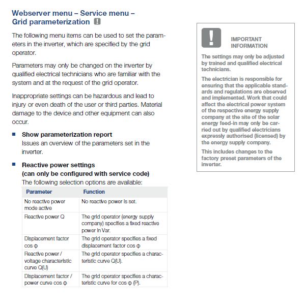
That's what I want. There is an installer only menu with these options which came out with the last firmware update... maybe my question had an effect. The last update you had the option on putting a set value in only.

I am 100% certain though that the installation company will have zero clue about it. Just like they had zero clue about putting a battery in. They didn't want me to have a energy meter in the first place.

reactive_kiaz7n.jpg
 
davidbeach said:
The inverter simply needs to hold PF at the meter rather than holding PF at the inverter terminals. Don't know that specific inverter, but within the current limits of the power electronics they can provide what ever power factor is desired.
Alistair_Heaton said:
That's what I want. There is an installer only menu with these options which came out with the last firmware update... maybe my question had an effect. The last update you had the option on putting a set value in only.

In order for the inverter to do this it needs to firstly know what the power factor is at the meter, it can obviously work out what it is at the inverter. Inverter OEMs will generally have their own product that suits their inverter for this purpose (as well as for zero export limiting).

EDMS Australia
 
AH,
This topic seems to have moved past the mass per panel subject you started with, and I'm late to the party. I just want to pipe up and say that I have a couple of panels that are a bit bigger than 1m^2 which I use for various projects/experiments. I carry them around by hand comfortably. They certainly don't weigh anything close to 100kg each... more like 20kg.

 
We sorted that out I screwed up my decimal points when moving from kN/m2 loading to mass. Its 11kg/m2 dead load without the frame and wires. Same with the other values. Sitting waiting for the Estonian log cabin expert to turn up to survey the barn to see what can be recycled and what has to be burned. A new roof is a certainty but I have zero clue about slotted logs pinned together with wooden pegs for load bear/shear bearing. The brother in law reckons quarter of a ton of moss from the forest is going to be involved.

 
Status
Not open for further replies.

Part and Inventory Search

Sponsor