Continue to Site

Eng-Tips is the largest engineering community on the Internet

Intelligent Work Forums for Engineering Professionals

  • Congratulations pierreick on being selected by the Eng-Tips community for having the most helpful posts in the forums last week. Way to Go!

Soldering issue.

Status
Not open for further replies.

itsmoked

Electrical
Feb 18, 2005
19,114
We have a pick-en-place running and am having a nasty problem with the subsequent reflow soldering.

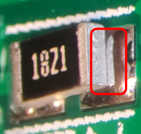
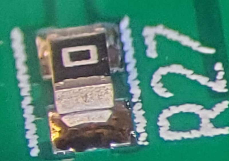
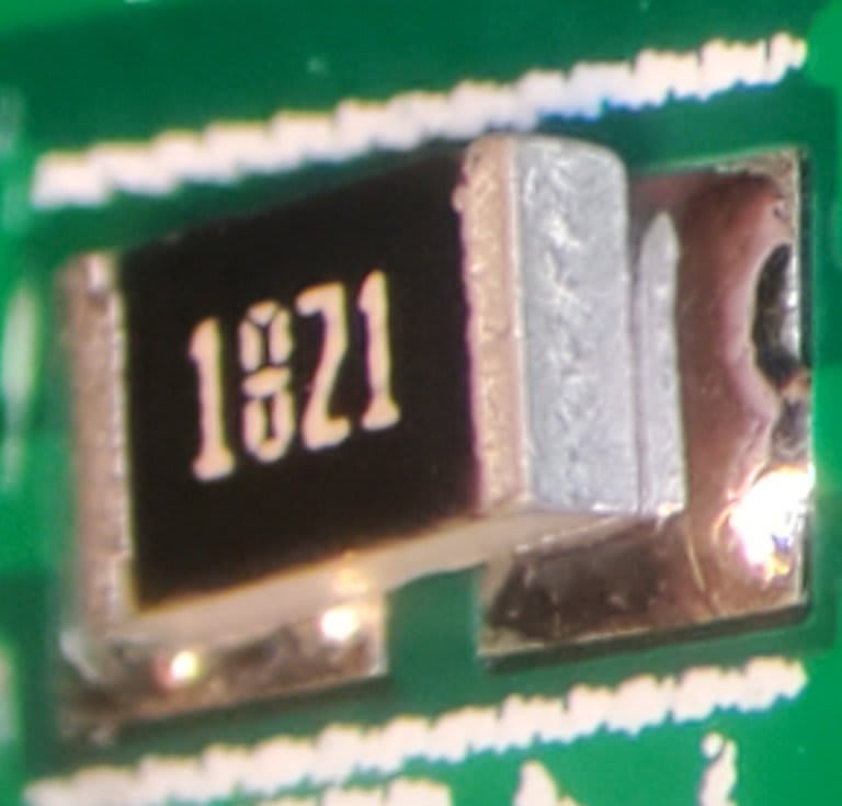
These pictures are examples of the problem. We get no tombstones at all. The joints that solder are excellent but each board has approximately 7 of these soldering failures. They're a nightmare as one has to look at every part under high magnification to spot them. Then, after one thinks they've found and fixed them all, boards fail test and extensive troubleshooting 90% of the time shows one of these that's been missed.

20191216_174750_1_azrqf2.jpg


20191216_174836_1_emiefh.jpg


Frequently we'll find the same side of the same part on multiple boards demonstrating this.

We're using ChipQuick lead solder about one screen number smaller than standard.

When we were using a "standard" temp profile. We had 32 boards out of 32 having this problem.

Running a test we changed the temp profile to exactly what ChipQuick specified. No improvement.
We added 5 seconds to the end of the profile peak. It didn't improve.

We added 5 more seconds (10 total) and it seemed to improve by about 40% less errors.


Suggestions?

Keith Cress
kcress -
 
Replies continue below

Recommended for you

Stop using lead-free solder?

It really looks like there is something wrong with the plating on the resistors.
 
They're not wetting. i.e. the parts.

- Old parts with oxidized terminals?
- Bad batch?

Those can be excluded if there are various PNs involved.

- Reflow temperature calibration off?

Check the oven temperature.

- Requires flux or paste?


Check the oven temperature, i.e. the calibration of the temperature sensor may have drifted off (and likely low).

How does flux get applied in a reflow setup? Is the paste supposed to do the job from the board side only, or do you have a way to flux the ends of the parts?
 
Definitely poor wetting of the end caps.

What flux are you using? When the big push to migrate from lead-bearing solders in the 1990's we had far better results using a water-washable flux with appropriate wash procedures than a no-clean flux which, of necessity, aren't particularly active. The water-washables by contrast can be pretty active at soldering temperature.

Another thing to look at would be the reflow temperature profile - especially the pre-heat to get the flux activated ahead of actual reflow itself.

 
Dave; Might have something there. All parts are pretty much non-leaded now so perhaps the fluxing is not best while using leaded paste on these non-lead parts.

VEBill; Solder paste, and it has the flux in it. Yes! Not wetting seems to be the problem. The oven is fairly new and I'd never seen the problem myself using it but now it's across town and the parts are being machine placed instead of hand placed. Hmmm, wonder if they are somehow not being mashed into the solder paste at all on an end.

Multiple part types are doing this but as I mentioned it tends to (mostly) be certain parts and some of them could be up to two years "in the bag".


btrueblood; Yeah, the flux is part of the paste. As far as I know adding more of your own would violate the paste. We haven't checked the oven temp... Guess I should do that.


IRstuff; Not following you buddy.. "Preform"?

Scotty; You got that right.. No wetting. There were actually two connections out of the approximately 130 failures out of ~6,500 joints, that the solder joint looked completely done but under high mag you could see about a half-mil air gap completely around the part's unconnected terminal. These were only found thru test failure troubleshooting.

We checked the flux first. It's AQUA washable 'must wash' solder so it's more active than the no wash.

I've always used non-leaded must-wash when I did them by hand but there are sooo many tiny variables between machine placed and hand placed, leaded/unleaded, just for starters like two days of assembly before reflowing verses two hours. Unleaded for starters is about 50C° higher. That's gotta have the chemical reactions of the flux scurrying about 5X harder.

Touching up these problem connections usually requires nothing more that touching the soldering iron tip to the connection and the solder jumps onto the component and surface-tensions right up it looking normal.
2zp6ucm.gif


Keith Cress
kcress -
 
What's the expiry date on the paste? When we still used rosin-based pastes they went downhill pretty quickly after the expiry date, with the flux losing solvent and becoming heavier and stickier - it wouldn't print nicely and components wouldn't bed into it. Not sure how the water-washables behave as they age as the chemistry is very different. I do recall that they were far more sensitive to the reflow temperature profile - too hot too early and the flux was consumed by the time the solder melted, too late and the flux didn't have time to work before reflow. I'd have a careful look at the thermal profile. conveyor speed, etc. We used to send a recorder through the reflow oven, but if it's a belt type then it's not too hard to do with a long thermocouple. If this is a commercial pick & place operation then they should have something capable of doing this for their own QA purposes.

Is there anything unusual about these parts in terms of geometry / size? They look fairly standard. Component aging is definitely a suspect, aged palladium-silver isn't good to solder to - one of my first tasks on the thick film hybrids line was to salvage a load of old printed alumina substrates with oxidised PdAg tracks.
 
Hi Scotty.

This is a drawer oven.
The paste is a couple of weeks old. One year minimum lifetime.
They aren't having any problems they see with any other assemblies just mine.
2zp6ucm.gif


The temperatures are correct. I'd say it's the chemistry.

Mine may have some two or three year old SMD resistors. I find this disturbing since they want everything in reels when on this screwy build with 37 different resistor values and 13 SMD cap values and most resistor values are single ones. That could mean in the future I'll be throwing dozens of nearly full reels away because the parts can't solder in a year or two?!?

They ran 8 temp profile tests using different but close solder profiles based on the the recommended profile by ChipQuick. It was a lousy statistical sample size of one board per test but the boards ranged from 14 unsoldered (USJ) joints on one board to 0 USJ points on another profile. Unfortunately we have no more boards to run on the build, to go back and run multiples on the 0 USJ profile to prove it wasn't an outlier.

I called to request they run my unleaded solder and they'd already done all the remaining boards. So now I'm in limbo for a few months.


Keith Cress
kcress -
 
Are the components with problems consistently from the same reel(s) or is it a more random distribution? Or conversely are there any types which are consistently behaving every time? Do the bad / good ones have anything in common, e.g. manufacturer, manufacturing plant, geometry, plating material, date code, etc? If you have a medium-power microscope are there any visual clues on the resistor chips, e.g. dulled finish, crystalline deposits, etc?

I'm not really familiar with drawer-type reflow ovens having never used one. The ones I worked on were all polymer belt or chain-conveyor types. Some chip types behaved badly with top-heat infra-red ovens but behaved far better with a belt type with significant bottom heat: I suspect different colours and/or surface finishes affected the IR absorbtion of the components so they heated at differing rates. You said temperatures were good, what about times? The dwell after flux activation is important, particularly on synthetic fluxes which water-washables tend to be. Things will have changed in the 20-odd years since I was in the industry, I imagine the fluxes are a lot better now - also bear in mind my experience is on thick film hybrids and not PCB's, although there are some obvious parallels.
 
Difficult to tell from the close-up pics, but are the non-wetting ends all thermally-relieved attachments to thicker copper? If so, that's a big clue that your pre-heat profile needs work. Beyond that, it's a flux issue... it doesn't necessarily need to be aggressive, but it needs to stay around long enough that both sides of the component wet at the same time and before the flux melts away.

Dan - Owner
Footwell%20Animation%20Tiny.gif
 
Dan, Early on we thought exactly that! It seemed to the crew that the problem was constrained to terminals on thermally isolated pads off the extensive ground planes. They told me this but as I'm the one with a nice microscope I didn't get the feeling it was only constrained to plane pads. It was about 50-50.

With the last 8 boards the temp profile was changed each single board reflow. A little longer preramp, a higher peak temp, both, etc. All based from the solder maker's recommended thermal profile. Over 7 of the 8 boards the Un Soldered Terminal counts ranged between 4 and 14..

The one board? It was run with a middle-of-the-pack-profile. Profiles with slightly longer ramps and slightly higher peaks (both spawning 4 (USTs). However the engineer running the oven, after a cursory inspection of the warm board still sitting in the oven drawer, "felt" there were some completely unsoldered sections and ran a second cycle on the board. It ended up having zero USTs on it.

Wasn't run hotter or any different just twice from a warm state.
What do you think that denotes?

Keith Cress
kcress -
 
Is this done as a single batch of boards with nothing done beforehand? If so, that could be the programmed profile is not what you're actually getting as the machine mass itself is providing a heatsink during the initial cycle.

Dan - Owner
Footwell%20Animation%20Tiny.gif
 
I agree with Dan that this could be a profile problem - is the profile programmed to follow the manufacturer's guidance, or is the profile measured with a thermocouple on the board to match the recommended profile?
 
The oven is fan forced and runs the temp profile closely to the programmed profile as programmed. Does that mean the board surface runs the profile accurately? I don't know. My cheesy little modded toaster oven I control by dint of a TC sitting on a board's pad. I'm thinking that's a much better way.

Keith Cress
kcress -
 
Status
Not open for further replies.

Part and Inventory Search

Sponsor