Continue to Site

Eng-Tips is the largest engineering community on the Internet

Intelligent Work Forums for Engineering Professionals

  • Congratulations KootK on being selected by the Eng-Tips community for having the most helpful posts in the forums last week. Way to Go!

Sole Plate to Rim Board Connection (Nail Strength) 2

Status
Not open for further replies.

GA_Engineer

Structural
Jul 9, 2021
14
I don't work a lot with wood but currently have a project utilizing LSL rimboards beneath wood framed walls, some of which will be shearwalls. I understand the mechanics of the shear transfer from the wall above using 16d nails from sole plate to the LSL and from the diaphragm to the LSL via the diaphragm edge nailing pattern. Then at the top plate below I would have a framing angle (like a Simpson A35) to transfer the lateral load from the LSL to the wall below. My question is how do I calculate the strength of the 16d nails connecting the sole plate to the LSL? In looking at NDS 2018 Chapter 12, I don't see any tables that adequately reflect this situation (side member being sawn lumber and main member being an LSL). I have found proprietary information for this situation for screws such as TimberLok and Simpson, but nothing regarding nails. I realize this might be a dumb question for some, but I appreciate any help I can get.


Wood_Shearwall_Detail_esajdp.jpg
 
Replies continue below

Recommended for you

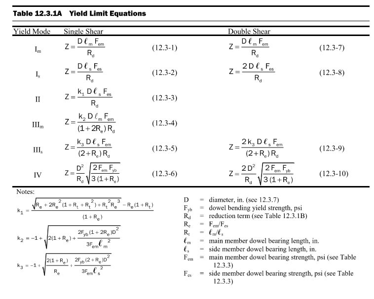
Looks like I will be spending some time calculating the capacity the long and old fashion way, by hand for these equations. I just wasn't sure if there was a table someone had created. You would think the LSL or LVL rimboard manufacturers would include this in their literature as it isn't hard and they only have to do it once.

Yield_Limits_nw5w5j.jpg
 
For lateral loading, you can treat it like sawn lumber. The manufacturers provide equivalent specific gravity values. LSLs are different for face and edge grain, I believe. So using the load tables/calculators that are available but selecting a species with a comparable SG should get you what you need.

I've found AWC's connection calculator to be a handy tool for quick checks.
 
GA_Engineer:
A few words of caution… Read that TrusJoist (Weyerhaeuser) pamphlet that Celt83 provided very carefully; every footnote, every table title, every one of their details for the implications of why they show things the way they do. They pack one hell of a lot of info into a pretty small pamphlet, and it all has some meaning in making their product work, or fit within the bldg. codes. Sometimes you have to read a bit btwn. the lines, based on your wood design education (or dig your textbooks out) to understand where they are coming from, or what they really mean. Those TJ Rim Boards were originally designed/manuf’d. to work with their TJI joists, pretty much prescriptively, and their TimberStrand LSL is basically a manufactured commodity product, in many/several widths, thicknesses and lengths which can be used essentially the same way as the rim board.

One thing to watch out for is that each manuf’er. of those materials has their own proprietary mech. properties, and various allowable stresses and other adjusted/equivalent values, etc., which you must live with. Thus, you pretty much have to know which product is going to be used on the job, know your local availability, or the builders purchasing wants. I would also check with the various suppliers floor trusses, rim boards, etc. to see that you have a reasonably good vert. settlement compatibility at the floor framing level. i.e., we know that a 2x10 rim jst. and 2x10 jsts. shrink vert. the same amount at each fl., is that true of your fl. truss and the LSL rim board? You usually don’t want to carry the ext. sheathing mat’l. continuous vert. through this fl. construction height region because there is too much vert. shrinkage/settlement in that couple ft. of ht. You put a spaced horiz. joint btwn. the sheets, which is then nailed off to the rim board (above and below the joint) to transfer diaphragm loads.

You should be able to find some testing and tabulations for nails and screw which are compliant with the IBC; some ICC-ES ESR reports, on nails, screws, plywd. and osb sheathing, etc. Also, some individual supplier/manf’er. literature like the TJ pamphlet abv. The guys who are doing this work every day will have to help you there, my collection of that kind of design material is getting kinda old, as am I. I just don’t collect it every time I see it any longer.
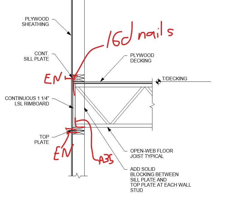
 
Just a thought on your load path. The arrangement of nailing and connectors necessarily assumes that any sheathing between the bottom plate and the top plate is not participating in the lateral load path. Shear comes from the sheathing into the sole plate, then into the LSL, then into the top plate, and finally back into the sheathing below. I have generally seen that an exterior detail like that will have sheathing continuous over the edge band member. If you can put a little control on the horizontal sheathing joint (to say the top of decking), then you could eliminate the A35 since you could provide perimeter nailing from the bottom sheathing into the LSL.

Robert Hale, PE, SE
 
Status
Not open for further replies.

Part and Inventory Search

Sponsor