TMcRally
Automotive
- Aug 17, 2007
- 153
I'm well out of my comfort zone sorry  . I would like to develop our own design and understanding. I have had quite a good look and only seem to find very basic or very advanced topics, I was hoping for some middle ground for dummies
Requirement...
Dave
. I would like to develop our own design and understanding. I have had quite a good look and only seem to find very basic or very advanced topics, I was hoping for some middle ground for dummiesRequirement...
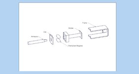
- latching solenoids
- I hope to get the maximum possible pull force at 12mm stroke. =/>12N...more is better.
- 24Vdc @ 3Amps, I will use these on existing sites that already have run cables and power supplies. Not ideal, but it is possible to increase the Amps a little if necessary
- The available size within the housing restricts the coil bobbin to 49mm long (clear space on the bobbin, not including the bobbin itself or latching magnets) and an OD of 25mm.
- These will have very low duty cycles.
- more coils the greater the force
- more current the greater the force
- more coils = longer wire = greater resistance = less current. The 2 variables, (number of coils and current) seem to be in opposition to each other for increasing pull force.
- suitable armature diameter
- Is there a "best" armature material
- Is there an optimum armature "energized" retracted position, with reference to the end of the coil.
- Wire diameter calculation
- I have been working with U shape open frames, not sure if this is optimal.
Dave