Continue to Site

Eng-Tips is the largest engineering community on the Internet

Intelligent Work Forums for Engineering Professionals

  • Congratulations KootK on being selected by the Eng-Tips community for having the most helpful posts in the forums last week. Way to Go!

Solenoid Valve Voltage Drop Issues

Status
Not open for further replies.

JuruteraWA

Petroleum
Mar 25, 2022
2
Greetings,
I have a set of solenoid valves that need 24V +/- 10% to operate properly. Unfortunately, my PLC is about 1000' away (with existing 16 gauge wires). My electric circuits is a little rusty. Will the following diagram work with the voltage requirements at the solenoids? Seems like it would if I put the power supply close to the solenoid. But I'm not sure how that 1000' to the PLC on the "-" side will affect the voltage.
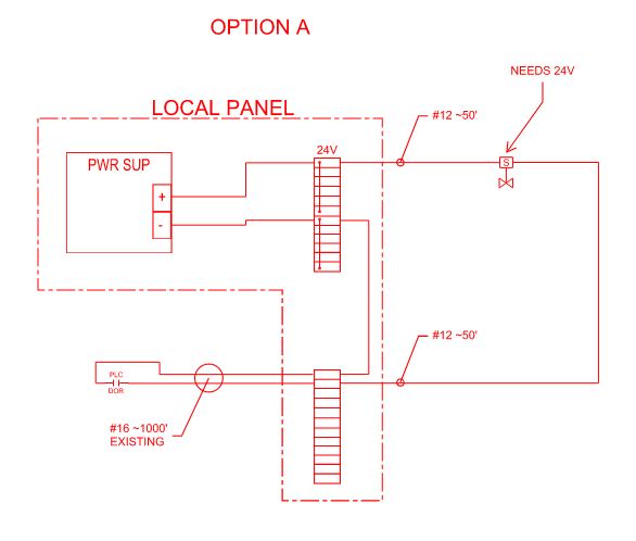
Option_A_akbs65.jpg


Option B would be to use an interposing relay. I'm hoping to avoid if possible (this is a SIF and would prefer to not add components to affect the achieved SIL). Any input would be much appreciated. Thank you!
 
Replies continue below

Recommended for you

We can easily tell you but we need more info!

What is the coil power of the solenoid OR its current draw?

Is it actually DC OR is it AC?

Ideally the solenoid spec sheet should state "minimum operating voltage". That would leave zero question about the results.

When you say "1,000 feet" is that the physical distance or the wire distance they're different by 2X.

Keith Cress
kcress -
 
@itsmoked Thank you.
Solenoid is rated at 21W. It's a DC circuit. I might not have been clear in my question. The distance from the "+" side of the power supply is 50 feet from the solenoid. Then the wire continues 1000 feet to a PLC contact (and yes, 1000 feet back). Question is, won't the voltage still be close to 24VDC at the solenoid since it's only 50 feet from the power supply? It's the "-" side that's confusing me.
 
You have a solenoid in series with two resistors. One resistor is from the power supply to the solenoid. The other resistor is the wire through the PLC contact and back to the power supply. The total voltage drop is 24V, but if 3-4V is dropped in the two resistances that may not leave enough to keep the solenoid.

16 gauge wire is supposed to be 4.016 Ohms per 1000 feet, so the second resistance is 8 Ohms altogether. If the solenoid takes 21W at 24V then that's about 0.9Amps. Going into 8 Ohms, then V=IR = 0.9Amp * 8 Ohms = 7.2 Volts, leaving only 17V to operate the solenoid. Add in the additional 100 feet of wire and the available Voltage is even less.
 
It's the voltage difference across the coil that determines the current.

resistance is roughly 4 ohms/1000ft for 16 gauge, so total of 8.4 ohms, plus coil resistance of ~27 ohm (21W/(24V)^2). Therefore, coil current will only be 0.67A or about 77% of rated current. You need to find out from the relay datasheet what minimum current is required to engage the relay.

TTFN (ta ta for now)
I can do absolutely anything. I'm an expert! faq731-376 forum1529 Entire Forum list
 
I concur with both 3DDave and IR's responses.

Having the supply next to the solenoid provides no real advantage because ALL the current still has to flow thru the entire wire loop back to the PLC and return from the PLC and thru the power supply wherever it is.

Many 24Vdc solenoids would operate with 17V but that's probably close to the low limit. That means that if anything lowers the voltage a weeeee bit more it might not work which will give vexing failures. Typically if the supply only runs the solenoid you check the PLC for the maximum voltage it can safely switch then crank up the power supply voltage to whatever that is so that once the aforementioned 7.2V is lost there's still something close to 24V available for the solenoid.

A PLC output block might switch 3-30V so you could use up to a 30V supply. Whenever the PLC turns ON the solenoid the voltage instantly drops to 22V, still enough to operate the solenoid reliably.

The alternative is to put the supply next to the solenoid with a single pole relay between it and the solenoid. When the relay is actuated and closes the solenoid gets the 24Vdc. Then the PLC only has to switch the relay coil which is probably about 2Watts or less.

2W / 24V = 80mA instead of 900mA.

Then only V=IR = 0.08Amp * 8 Ohms = 0.64 Volts is lost. The relay runs on 23.3V which is no problem at all.

You may run the PLC output with the same 24V supply that's at the solenoid. Now the 900mA is only run a few feet and the 80mA makes the 2,000ft trudge.

You would most definitely need to put a clear schematic at each end so someone faced with troubleshooting a bad solenoid, relay, power supply, wire run, or PLC would understand this non-typical setup.

Keith Cress
kcress -
 
Crazy thought:

Can't you just not ground the negative of the power supply and the PLC output common and switch the valve?.

 
Status
Not open for further replies.

Part and Inventory Search

Sponsor