Continue to Site

Eng-Tips is the largest engineering community on the Internet

Intelligent Work Forums for Engineering Professionals

  • Congratulations KootK on being selected by the Eng-Tips community for having the most helpful posts in the forums last week. Way to Go!

Solid Extruded Tube, collapsing and rippling in Dynamic Explicit Step 2

Status
Not open for further replies.

tomtom412

Bioengineer
Jan 15, 2018
12
Hi all

I have a simple analysis, where a long tube is displaced into a large tube that features a bend. The idea is to look at the stress distributions along the tube as it deforms around the bend.
I have been using a dynamic explicit step to run this, using shell geometries to date, and it runs fine. However, once I employ solid geometries, and long lengths, the tube that is being displaced "ripples" when it should just translate in one direction, and it also flattens out and collapses under itself in some way. Attached picture describes what I am finding.

Is this a product of using the dynamic explicit step? I have attached the input file, if anyone could give me some insight into what may be happening.
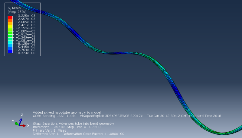
Rippling_LSST_wjbrqu.png


Regards,
Tom
 
Replies continue below

Recommended for you

The element type C3D8R is quite bad when used with one element through thickness and bending deformation. Try again with C3D8I.
 
Be careful when using C3D8I also - it is much more sensitive to aspect ratio (likes to be a perfect cube).

Check your artificial strain energy.
 
Not sure why you need a tie constraint at all. The geometry you are working seems benign enough to let you have a continuous mesh. If you are going to be a modeler, meshing is an essential aspect that you must become good at.

Also, unless there is real need, it is better to have realistic material properties assigned to all materials in a model. So, while assuming something is rigid can be okay in some situations, it can cause other difficulties such as in contact penalty stiffness determination by the code, artificially high contact energy, etc. which can then manifest in unrealistic accelerations.

*********************************************************
Are you new to this forum? If so, please read these FAQs:

 
IceBreakerSours said:
Not sure why you need a tie constraint at all. The geometry you are working seems benign enough to let you have a continuous mesh. If you are going to be a modeler, meshing is an essential aspect that you must become good at.

So I was having difficulty meshing the transition region (sloped), with the hex elements that I used for the other 2 regions. a free tet mesh was all I was able to apply, despite numerous attempts at partitioning. As I am new to the software and am still learning, perhaps I am missing a way that I could partition this region to allow for a continuous use of a single element type?

Regards,
Tom
 
Status
Not open for further replies.

Part and Inventory Search

Sponsor