Continue to Site

Eng-Tips is the largest engineering community on the Internet

Intelligent Work Forums for Engineering Professionals

  • Congratulations Toost on being selected by the Eng-Tips community for having the most helpful posts in the forums last week. Way to Go!

Solidworks simulation - Component contact and stress singularity

Status
Not open for further replies.

RBVT

Mechanical
Jun 28, 2019
4
Hi all,

I run a FEA on an assembly and I am not sure if I can trust my results or if they are "polluted" by a singularity.
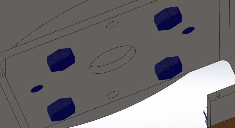
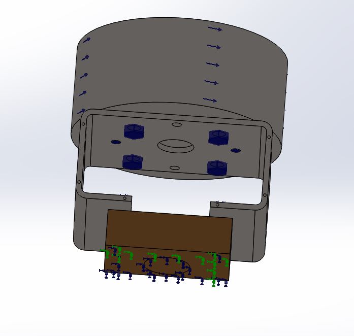
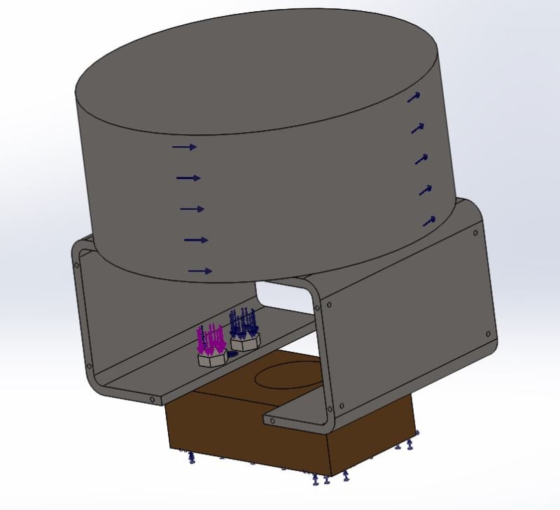
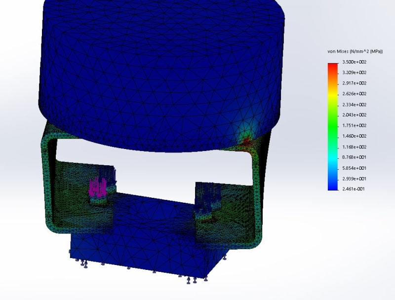
The top part, a gearbox generate a torque transmitted through some bolts an pins connectors to the folded parts, the Mounting Box. (Enclosed "Gearbox connection")
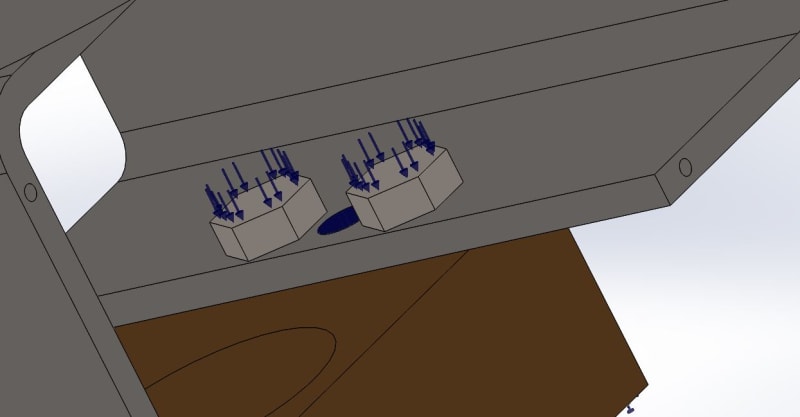
This mounting box is connected to a fixed body thanks to a pin connector and some 3D bolts. (Enclosed "Body connection")
My assumption is that the gearbox connection is rigid when the body connection can allow some movement under the bolts if the bolt preload is too low.
I applied a force on the top of the bolt to model the preload and I set a friction of 0.1 between the bolt head and the Mounting Box and between the Mounting box and the body.

The assembly seams to deform as expected, when increasing the torque I can see some movement under the bolt until the box hit the bolt diameter.
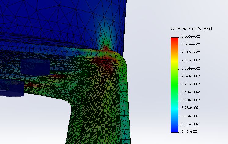
My problem is that I get very high stresses on the corner of the mounting box and I am wondering if I should worry about it.
I believe my simulation allow me to correctly plot the displacement but that the stress isn't accurate because of this singularity.
How can I get correct reading of the maximum stress in this corner?

I tried simplifying the model by only keeping the mounting Box and I don't have at all the same kind of stress.

Any though about my results?

Thanks a lot.

Gearboxe connection
Gearboxe_connection_igp1j3.jpg


Body connection
Body_connection_zkjvbt.jpg


Deformation
Deformation_yxr1cz.jpg


Stress concentration / singularity
Stress_concentration_ebc4ud.jpg
 
Replies continue below

Recommended for you

A bit more information will be necessary so let me ask you a few additional questions. What is the interaction between gearbox and mounting box ? You said that you want this connection to be rigid but did you apply any contact between these two parts (be it bonded or no penetration) ?

Also is there a contact interaction between the bolt shank and holes ? What is the scale of the deformation plot ? Isn't it deforming too much ?

Can you show a picture with those pin connectora. I'm not sure where they are applied.

Finally, I would rather apply preload force on the part of the shank instead of the head but maybe this approach will work too.
 
Hi,

The gearbox to mounting box contact is a no penetration contact (node to surface).
The Mounting box to body contact is a no penetration contact (node to surface) with a friction coefficient of 0.1.
No penetration contact sets (node to surface) under the bolt head.
No penetration contact sets (surface to surface) between the bolt diameter and the body bolt hole.
No penetration contact sets (surface to surface) between the bolt diameter and the Mounting box bolt hole.

Yes of course the deformation scale was 5 but the deformation remain quite large (around 3mm in X and Z direction).
I performed a design study increasing the torque and I saw the model was acting as I was expecting.
Their is slow deformation until the torque is high enough to overcome the bolt friction.
At this moment the deformation increase quickly, the bottom of the mounting box is moving, until the Mounting box come into contact with the bolt.
The deformation goes slower after that.

I performed some trials on this assembly and I get very similar displacement.
In fact I used my trials to help me set the friction coefficient.
Displacement_curve_gl0sph.jpg


I am not surprised to see high stresses appearing but I wasn't expecting them to be that high.

The gearbox pin connectors are on the same PCD than the Gearbox bolts.
Pin_connector_Gearbox_kr4tyw.jpg


The body pin connectors are between the body bolts
Pin_connector_Body_uzc9ap.jpg
 
Make sure that there are no initial gaps between the surfaces in contact that the selected contact algorithm may not catch (most types of contact definition in SW Simulation can't handle initial gaps).

For me this stress concentration doesn't look so bad. It seems that the gearbox is deforming slightly downwards and touching the mounting box. Due to the torque stress concentration appears around the point of contact. Investigate the remaining concentrations that can be seen on the first results picture and try to determine their causes.
 
If stress is the result you are ultimately looking for I would consider refining the mesh. Working with two elements trough the tickness, I would use more. But it also depends on the element firmulation and perhaps you have higher order eleents.

I would actually use a plate model för this if I understand the geometry correct. Also, it should not be impossible to get a rough estimate of the stress level by hand.

Thomas
 
Hi,

Thanks for your answers.

Yes I know my mesh isn't really adapted for a final study.
At the moment I am still running draft mesh as I wanted to get rid of the stress singularity first.
I ran jacobian 4 mesh in standard quality but the results are similar.
How many elements within the thickness would you recommend? Between 3 and 5?
What is the effect of using higher order element? Is it similar to a mesh refinement?

The singularity should only affect the results locally but I am not sure how far form the singularity I can read correct results.
Any advice?

I will try to use sheet metal for the simulation to see if I get different results.

Concerning a hand calculation I don't know how to simplify the model.
The torque isn't acting around the beam axis and the Mounting Box is too short to be considered as a beam.
Were you thinking about a particular calculation?

Thanks again.
 
You should use at least 3 elements per thickness. There are two types of mesh refinement: h (decreasing element size and thus increasing mesh density) and p (increasing element order). In SW Simulation default elements (high quality mesh) are second order tetrahedrons, draft quality mesh uses first order elements.

It's hard to say how far you should be from this stress concetration to make use of Saint-Venant's principle. But I think that correct results can be found pretty close from it.

I agree that it may be hard to calculate it analytically.
 
From what I can see you have a circular cylinder (the gear box) mounted on top of a C-shaped folded part (the mounting box). The loading is a torque on the cylinder.

The peak stress seems to be in one corner of the mounting box. Why is it only in one corner? Isn't there some symmetri in this?

Regarding an analytical solytion. The intention was to get a rough estimate, not an exact solution. Just to ensure that the results from the software are reasonable.
One way would be to study the vertical parts of the mounting box and and simplify it to four vertical strips. Than you would have the torque acting as a combination of bending in the four strips and shear supported by the plates between the four strips. The estimate the width of the strips, use the figures that you have shown us here.

If you look at how the models deformations and stresses you should be able to get a feel for how the force is distributed in the system.

Thomas

 
Hi,

I run additional analysis to try to understand if the stresses I get are true stresses or singularities.
I am quite sure they are singularities but it doesn't mean I can completely ignore them.

First, I run a convergence analysis and the stress seams to be infinite at the contact edges of the model.
Then, I run several other models playing with the gearbox dimensions and removing the gearbox (see file attached).
I believe the singularity appear as the corners of the box are moving upward and clockwise due to the torque creating a linear contact along the edge of the Gearbox (area = 0).

How can I get a true stress considering the mounting box / Gearbox contact?
Is it even possible?
Should I just ignore the contact stress by removing the Gearbox?

Thanks a lot.
 
 https://files.engineering.com/getfile.aspx?folder=546e1a30-ace1-45ea-add3-c8d86ae231de&file=Mb_Stress.docx
Hi
What I noticed is that your peak stress has been reduced from 350 MPa (?) to 200 MPa.
I can only assume that it id a stress you choose in the postprosessor for the color scale. I would set it much higher. I want a location för the peak stress, a point, not an area.

Then I would remove the contact conditions but keep the bolts. Are there still peak stresses, and if there are, where are they?
Another test would be to set a yield stress and run a nonlinear analysis. How does the yielding effect the deformations?

Haw you checked the contact stresses? They can be very high in some situations.

Before assuming that it is a singularity I would look at the things I have now mentioned.

Thomas
 
Is the maximum operating torque more than 400 Nm?
Do you need to maintain some alignment/concentricity between the cylindrical gearbox, and the hole indicated the "fixed body?" The inclusion of pins make me think you do.
For most machines and shaft couplings that concentricity needs to remain within .002"/.05 mm under all operating conditions.

When you say the deflection, where is it measured/predicted, and what direction?
Is the mounting box so open to allow assembling a coupling, and to access the bolts securing the mounting box to the fixed body?
If there is a coupling in there, how are you going to be able to assemble the coupling AND assemble and tighten the bolts securing the mounting box to the fixed body?

The way the feet of the mounting box are "doing the twist" I'm guessing the bolt preload is too low, as I think you already suspect.

The torsional stiffness/resistance of the relatively thin sides of the mounting box bound to be terrible.
Is the loading anywhere near the actual operating loads, and is the > 2 mm deflection the corners of the MB feet twisting as shown?
That suggests to me the MB needs to be 2 or 3X thicker, made of steel if it is currently aluminum, or simply be replaced with closed sections.
 
Status
Not open for further replies.

Part and Inventory Search

Sponsor