Good morning,
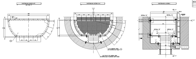
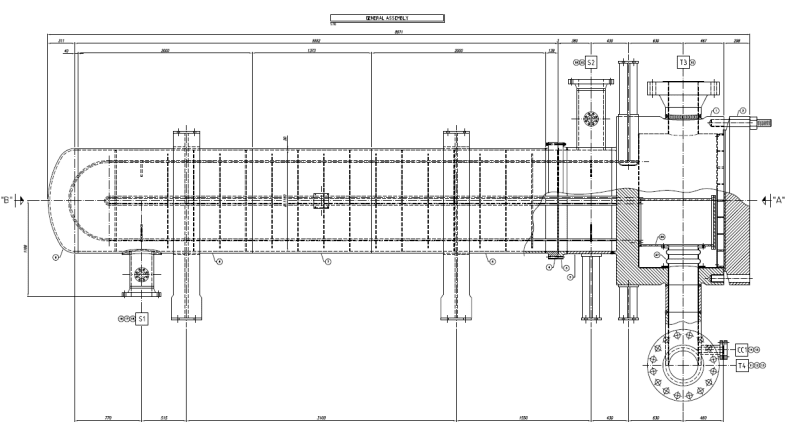
I need help for a FEA of a partition box inside a channel of an high pressure heat exchanger that I am running for verify the component according to ASME VIII div. 2 Design by Analysis (I attach construction drawings):
Design pressure (tube side): 10.97 MPa
Design temperature: 450°C
Material: ASME SA 240 TP 321
For the material I manually entered its mechanical properties at 450°C.
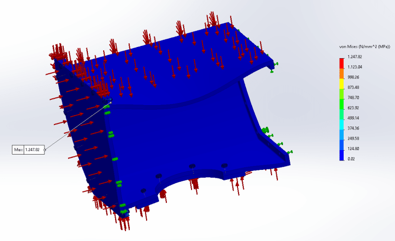
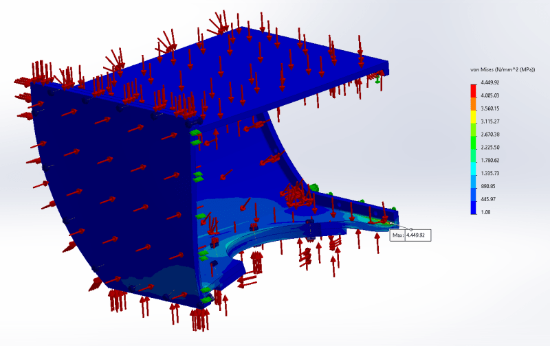
The simulation was performed with the following loads:
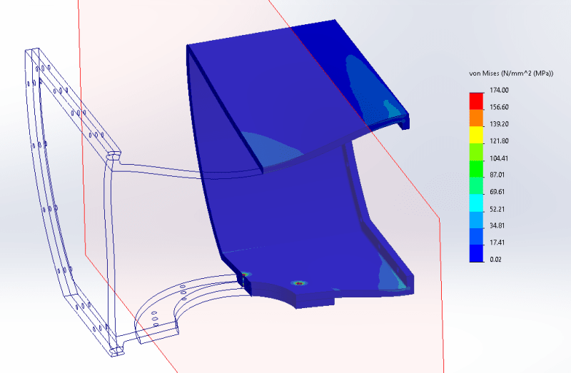
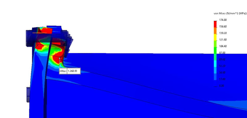
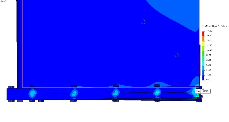
Simulation 1 (External pressure: 0.05 MPa; internal pressure: 0 MPa) ---> max Von Mises 1247 MPa
Simulation 2 (External pressure: 10.97 MPa; internal pressure: 10.92 MPa) ---> max Von Mises 4449 MPa
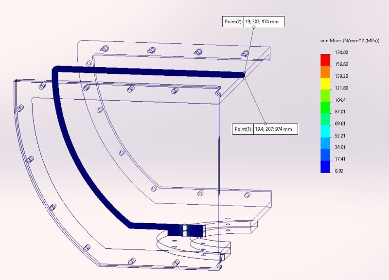
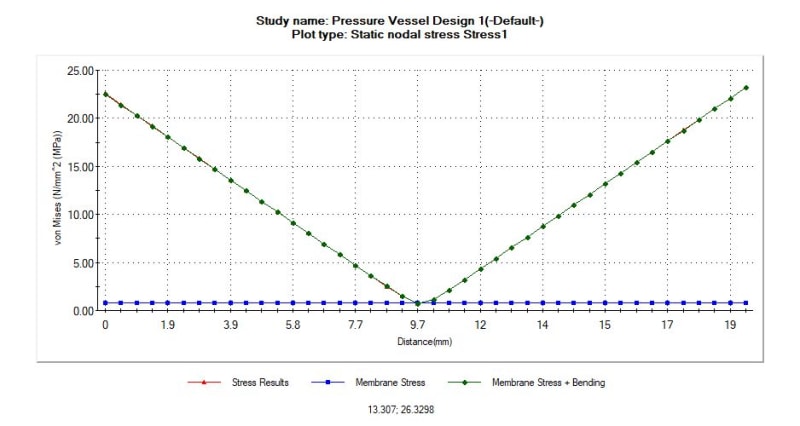
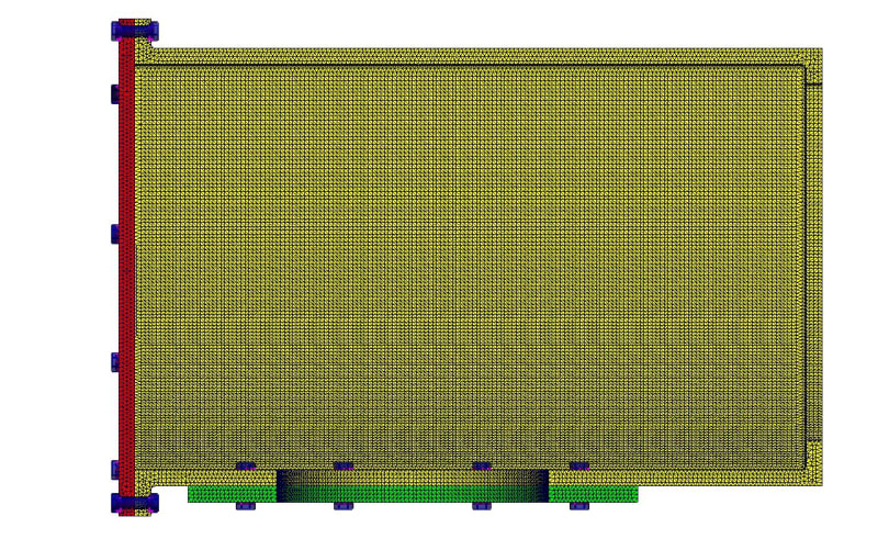
In the images are shown the trends (I used the symmetry constraint) and the behavior of the first simulation seems to me much more adherent to reality..
The same mesh, constraints and contact conditions were used.
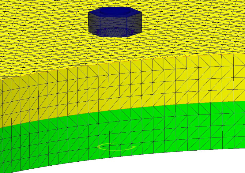
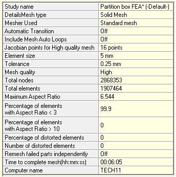
My first question concerns the different results obtained with the same pressure difference between the inside and the outside: can this difference be due to a coarse mesh? The maximum Aspect Ratio is 187; I know that ideally it should be less than 5 to get good results, but I ran the simulation with this mesh just to understand how to refine it later and where. In addition, the maximum values obtained seem to me exaggerated (even if they are present in very small areas.
I would then like to understand how to consider the expansion joint present in the original drawing and understand why this was used. The displacement at that point (lower part of the partition box) is on the order of 0.2 mm. Do I have to consider the pressure thrust or I consider it automatically absorbed by the joint (otherwise why was it inserted?)?
I have not inserted any force due to pressure thrust in these simulations.
Thank you for your help.
I need help for a FEA of a partition box inside a channel of an high pressure heat exchanger that I am running for verify the component according to ASME VIII div. 2 Design by Analysis (I attach construction drawings):
Design pressure (tube side): 10.97 MPa
Design temperature: 450°C
Material: ASME SA 240 TP 321
For the material I manually entered its mechanical properties at 450°C.
The simulation was performed with the following loads:
Simulation 1 (External pressure: 0.05 MPa; internal pressure: 0 MPa) ---> max Von Mises 1247 MPa
Simulation 2 (External pressure: 10.97 MPa; internal pressure: 10.92 MPa) ---> max Von Mises 4449 MPa
In the images are shown the trends (I used the symmetry constraint) and the behavior of the first simulation seems to me much more adherent to reality..
The same mesh, constraints and contact conditions were used.
My first question concerns the different results obtained with the same pressure difference between the inside and the outside: can this difference be due to a coarse mesh? The maximum Aspect Ratio is 187; I know that ideally it should be less than 5 to get good results, but I ran the simulation with this mesh just to understand how to refine it later and where. In addition, the maximum values obtained seem to me exaggerated (even if they are present in very small areas.
I would then like to understand how to consider the expansion joint present in the original drawing and understand why this was used. The displacement at that point (lower part of the partition box) is on the order of 0.2 mm. Do I have to consider the pressure thrust or I consider it automatically absorbed by the joint (otherwise why was it inserted?)?
I have not inserted any force due to pressure thrust in these simulations.
Thank you for your help.