Continue to Site

Eng-Tips is the largest engineering community on the Internet

Intelligent Work Forums for Engineering Professionals

  • Congratulations KootK on being selected by the Eng-Tips community for having the most helpful posts in the forums last week. Way to Go!

SolidWorks Sketch Orientation 1

Status
Not open for further replies.

GhassanK

Aerospace
Oct 5, 2023
3
I am transitioning from CATIA (10+ years) to SolidWorks, and I am wanting to know the limitations of SolidWorks or workarounds to do some functions I’ve grown accustomed to in CATIA.

When creating a sketch in CATIA, you have the option to do what is called a “Positioned Sketch.” Basically, it allows you to define the origin, and horizontal and vertical axis of the 2D sketch. You may use planes, lines, axis systems to define the orientation of the sketch. Once you’ve defined the orientation, when you edit or open the sketch, it will always default to that orientation. Also the horizontal and vertical definition are based off your new defined H and V 2D axis.

SolidWorks on the other hand, defaults all sketches with the z-axis down. There is no user-friendly way to orient your sketch. Sometimes it is difficult or challenging to create a profile at a set orientation. Some orientations are easier to view or work with than others. I have been unable to find an easy way to do what CATIA does, the closest I’ve come across is using the “Modify” function in the Sketch tool.

Does anybody know if SolidWorks has a function for doing what CATIA does? Do you all SolidWorks designers just work with the orientation defaulted by SolidWorks? Thanks.
 
Replies continue below

Recommended for you

GhassanK,

SolidWorks' default behaviour is to apply horizontal and vertical constraints to your sketches. I hate, and I make a point of disabling it. I have been playing with OnShape, and I wish I could disable it there. When doing my first sketch, I fix either a point, or two lines to the origin. Then, I make one line horizontal or vertical. I make everything else parallel, perpendicular or angled.

In SolidWorks, you attach your sketch to a plane. There are all sorts of ways to position a plane to the orientation you need for your sketch.


--
JHG
 
Hello,

After doing a bit more research, I found that the “Align Grid/Origin” tool is more of the function I need that is capable of changing the default orientation of the sketch. However, it is very limited in comparison to what CATIA can do. From what I can understand, when defining the new origin and axis using “Align Grid/Origin” you can only select model features. It does not let you select sketch features or reference geometry such as a plane, axis, or point.

The “Modify Sketch” feature is not very useful, since it does not tie in to any geometry and must be manually updated if the model changes. At least, the “Align Grid/Origin” will update the sketch orientation with changes to the model.

Is there a better way of orienting the sketch in SolidWorks?

Below I’ve included a YouTube link of what I am trying to accomplish with SolidWorks. I just don’t know if this is a feature only exclusive to CATIA.

 
I hate to say it, but Solidworks is not Catia so you will have to do it like Solidworks does.

I don't see the problem, but I have never used Catia. I start a sketch on a plane and create my 2D sketch around the origin. The first thing you should be doing before you make your first sketch is to determine which orientation you want to start in. What is going to be my X, Y, or Z plane and work in that 2D sort of space (since sketches are 2D). Don't overcomplicate your sketches because you will back yourself into a corner early and you won't be able to fight your way out since you are new to SW. I have been using it for several years and I can always find a way out but I also don't deliberately back myself into a problem either.

The YouTube video you posted looks like he is defining a plane in a random space. if that is true then no SW cannot do it like that. You will have to make geometry to make planes. Key note not all sketches need a feature. Those are called Construction sketches. They are used to make planes or control locations etc... Everything is derived from the origin point. SW space is spherical and the Origin is at the center of its universe. I think the kernel space is like 500m in every direction from the origin or something like that. Not making parts off the origin is going to cause you a lot of issues especially when you are zooming and panning.

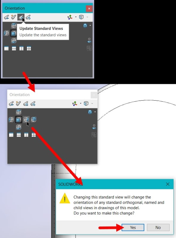
Watching Catia go through that process looks hard and complex to me. a lot of clicking and a lot of typing. I pick a starting point and go with it. I can always change the orientation. however it does not change the XYZ, but I can make my front view my right view. For example if I am looking at the front view and I want it to be my right-side view then I click the space bar and select the 3rd telescope. select the right side, it gives me a message I say yes, and tada the front is now the right.
View_ktc019.jpg


I would keep these things in mind:
1) Build at the origin.
2) think about which plane you want to start in.
3) Use construction sketches to build more planes or to reference sketches from
4) if you have not gone through the tutorials yet I would recommend you check those out. Very helpful when getting started.
5) Remember you are learning new software and it's not going to be anything like what you are used to.


Scott Baugh, CSWP [pc2]
Mechanical Engineer
Ciholas

"If it's not broke, Don't fix it!"
faq731-376
 
Hi, GhassanK:

I agree with Scott's assessment. You need to unlearn what you know. Then go through Soliworks' tutorials. You will be amazed how much more efficient Solidworks sketch functions are as compared to Catia.

Best regards,

Alex
 
Status
Not open for further replies.

Part and Inventory Search

Sponsor