Continue to Site

Eng-Tips is the largest engineering community on the Internet

Intelligent Work Forums for Engineering Professionals

  • Congratulations KootK on being selected by the Eng-Tips community for having the most helpful posts in the forums last week. Way to Go!

Sparkplug Clamp Pickup Sensor Circuit Fluke RPM80 1

Status
Not open for further replies.

MRSSPOCK

Mechanical
Aug 29, 2010
303
For anyone interested . . .

I looked for a while and tried different suggestions regarding how to create a sparkplug clamp / pickup which would produce a half decent and consistent signal.

I didn't have much success so I just took the plunge and bought a Fluke RPM80.

The output is excellent.

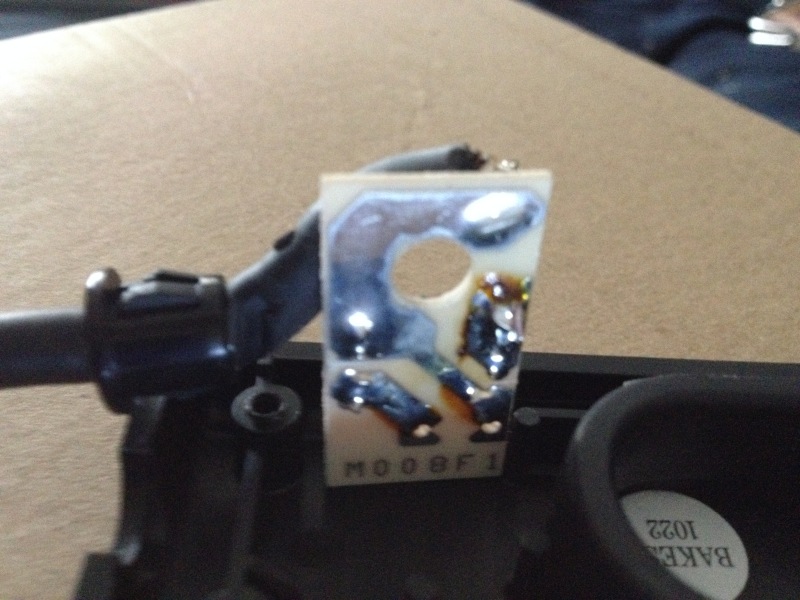
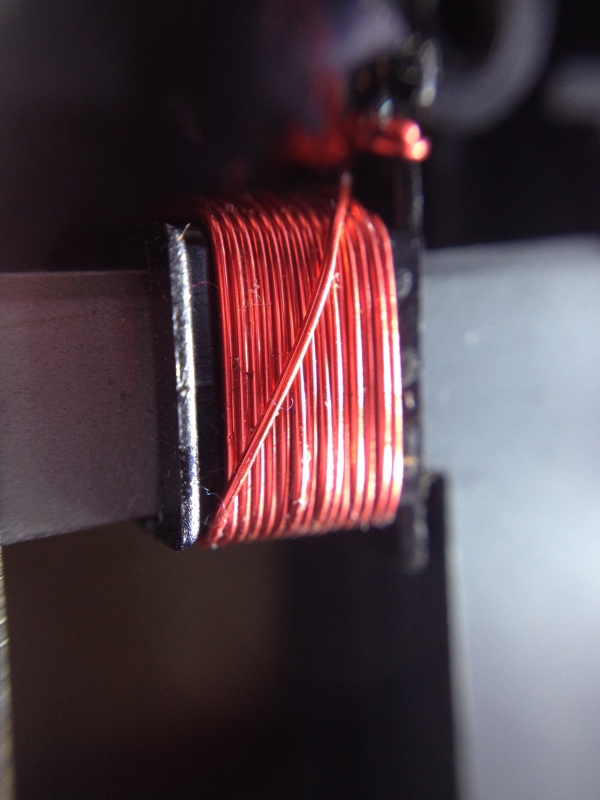
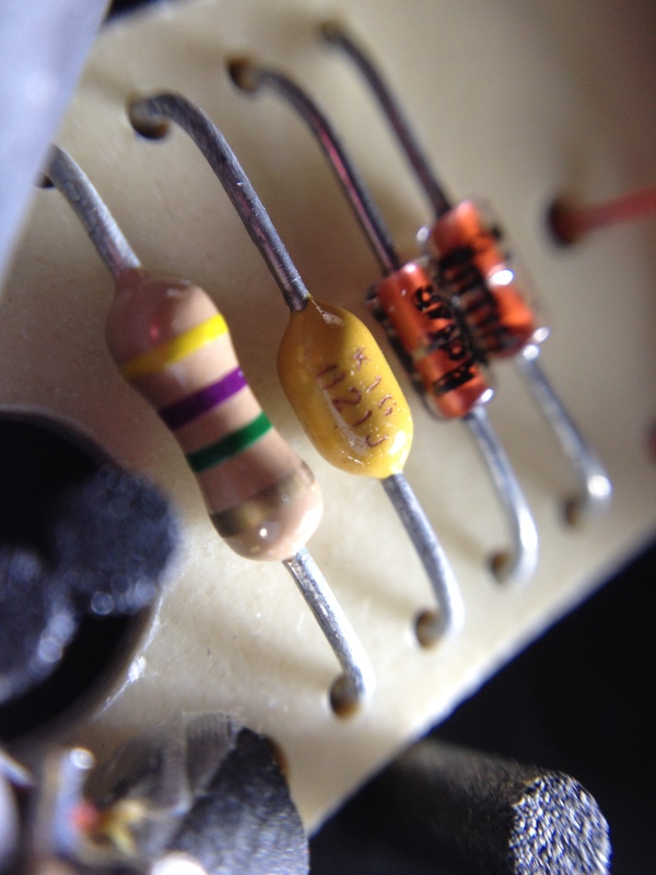
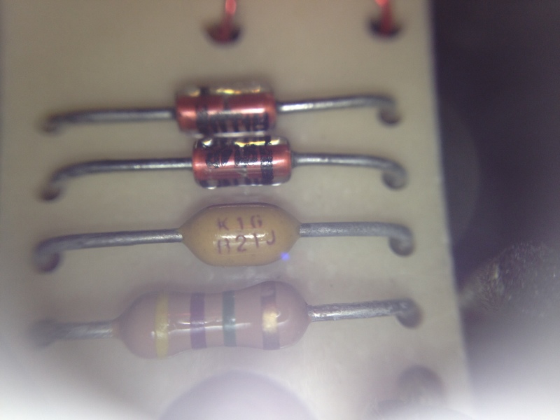
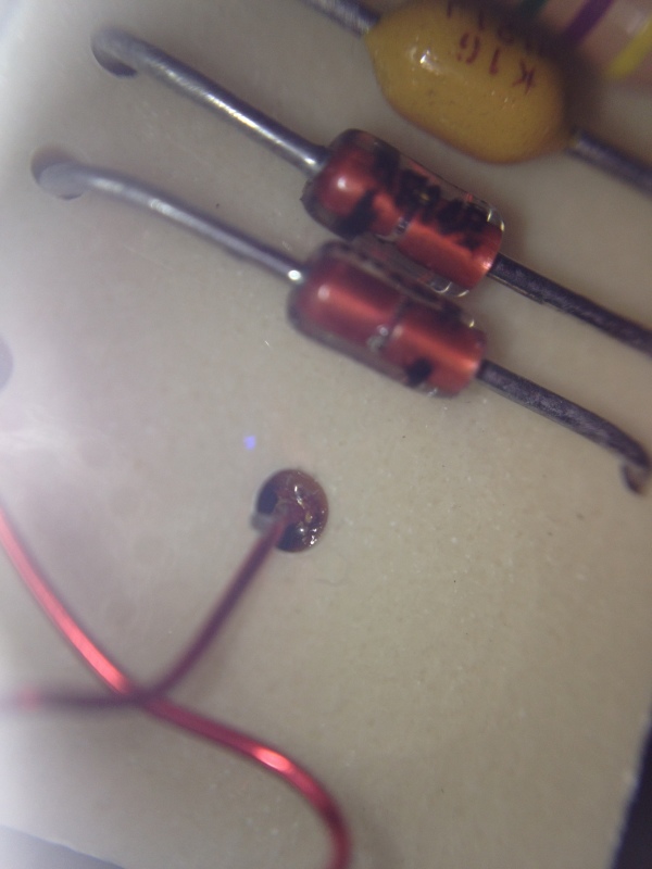
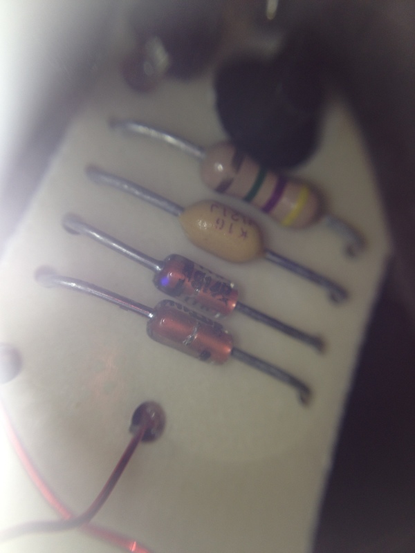
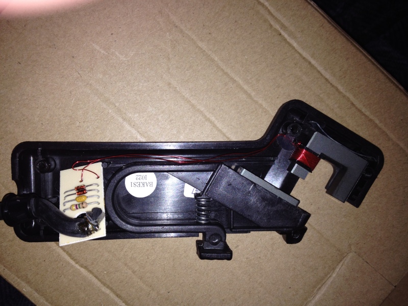
Here are a few photos of the internals.
IMG_0117_vsbald.jpg
IMG_0116_love29.jpg
IMG_0113_fq6hjl.jpg
IMG_0112_jcadhi.jpg
IMG_0101_pjc4ok.jpg
IMG_0093_eaycmp.jpg
IMG_0092_cvxmnd.jpg


Unfortunately these are the best photos I could manage to take, and even with my microscope I still can't read what is printed on the diodes.

Is it possibly 914, on a least one of them?

There are 16 turns of 0.014" wire on the ferrite, and the ferrite measures 1 inch square, and the cross section is 0.25" x 0.25"

The screen of the main coax cable is soldered to the main solder mass that you see on the board underside, and the core of the coax is soldered to the pad nearest the resistor, like you can see on the first image.
 
Replies continue below

Recommended for you

Do 1N914 still exist? A 1448 seems more plausible. But I would bank on zeners. Don't see any reason for a .7 V voltage drop. But a lot of reasons for a 5.1 or 10 or whatever limit.

4.7 Mohms looks awfully much in an application like this.

The secret for successful operation is probably in what ferrite you use. I would guess a hi-permeability medium frequency quality.

Gunnar Englund
--------------------------------------
Half full - Half empty? I don't mind. It's what in it that counts.
 
Oh, teardowns are fun.
Perhaps "1N3" is hidden under the diode and it's actually "514A" on the next line. 1N3514A sounds plausible... That would make it a 6.8V zener.

STF
 
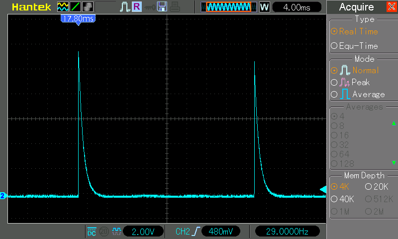
If you have oscilloscope data, that would be good. According to the Fluke 78 manual, the RPM80's output appears to be limited to 5.7V, so it's likely that you do have zeners in the pickup

TTFN (ta ta for now)
I can do absolutely anything. I'm an expert! faq731-376 forum1529 Entire Forum list
 
Did you see this in the manual ?

2-12.
RPM
Function
The output signal pulses of the RPM80 Inductive Pickup are divided by input resistors
R40 and R41, then applied to comparator U4. Resistors R42 and R43 set the trigger level
for U4 (and the protection clamp voltage for Q12), while R44 and R45 provide
hysteresis. When Q13 is turned on, R47 parallels R43, resulting in the lower input trigger
level. Q13 off produces the higher input trigger level. [highlight #EF2929]The lower trigger level is
annunciated on the display as a 4 V range, while the higher trigger level is annunciated
as a 40 V range.[/highlight] The output of U4 drives the frequency counter in U1. To convert to
rpm, the frequency is multiplied by 60 for RPM1 (1 revolution/spark), or 120 for RPM2
(2 revolutions/spark). The 10 A input serves as a common for the RPM input. Fuse F1
must be intact for RPM to work
 
UPDATE

I just had another look with another microscope.

They're both 914B

I recreated the circuit (using 2 off 1N4148 diodes instead), and built it into an old timing light clamp on pickup.

The output is identical to the Fluke.
 
I made one of these in college as part of one of my classes. That was too long ago to provide any useful information though. I do remember we got a very good pulse to work from to get RPM's. Good luck.
 
Status
Not open for further replies.

Part and Inventory Search

Sponsor