Eng-Tips is the largest engineering community on the Internet

Intelligent Work Forums for Engineering Professionals

Speccing a Brake Resistor with missing information

Status
Not open for further replies.

MitchusMaximus

Electrical
Jan 25, 2023
16
0
0
CA
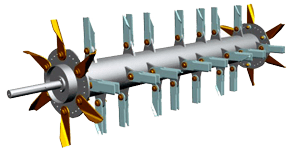
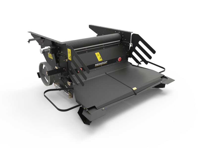
Hi, all. I work in VFD and electrical controls sales, and I have a customer who is looking to apply some faster braking to his VFD driven motor when he is balancing straw choppers. We are driving a 40HP 1725 rpm motor, being run at a top speed of 1294 rpm. He did some experiments and recorded the time to decelerate the the load as about 30s from the top speed. The worst case duty cycle the resistor would deal with is 10s/85s (acceleration, run time, deceleration time, and rest time adding up to 85s, decelerating for 10s at the longest.) or around 12%. I've run across some application notes on sizing the power rating of your resistor based on the braking torque needed and the braking duty cycle, but I am missing a crucial piece of information to work that out, that being the moment of inertia of the load. I believe the mass of the chopping assembly is about 200kg, but I don't know to work out the moment of inertia for such an irregular shape (see attached images for examples).
Can I manipulate some physics formulas with what I have given and come up with an estimated value for a moment of inertia, based on my angular deceleration? Or is this just something I can't theorize my way out of and I need to get their mechanical guys to figure out?
We are also using a braking unit that has a minimum braking resistor value of 4Ω, and the motor is rated at 230VAC.

Cheers
Drum_rvbhet.png

Straw_Chopper_v2dl8q.png
 
Replies continue below

Recommended for you

You could base the size of the resistor on the motor size. 40Hp is around 30KW. The VFD should prevent overloading the motor in deaccel, so 30KW would be the max wattage. You could probably go half that amount as the motor slows down the max power available also decreases.
 
Can you look up the shipping weight of a replacement rotor assembly if you were repairing one?


" We are all here on earth to help others; what on earth the others are here for I don't know." -- W. H. Auden
 
If you size it for the motor power at 50% duty cycle it will surely work. 50% is acceptable here because the accel time and decel time have to be equal at the same motor power. More specific information may let you select a smaller resistor but you may as well play it safe.
 
If you have a drawing of the item with at least a few dimensions -

For example the moment of inertia is simply m*r^2, so the cylinder, if the wall is thin, could be as simple as the length*diameter*pi*wall thickness as the volume, multiply that by the density (probably steel) and that times the square of the radius.

Similarly, the tabs have a center of mass at the center of each tab, so one can calculate the radius to each of those. The mass of each one will be length * width * thickness * density. Again, multiply by the square of the radius to the center of each tab. Of course multiply by the number of tabs.

There is a small contribution for moment of inertia about the center of each tab, but that can be ignored for this case.

I would also ignore the center shaft and the fans at each end; the effect of those will be smaller than will make a critical difference. If they would account for more than 5% I'd be surprised.

Or, and just spitballing here, you could ask if their CAD guys would use the software to calculate the moment of inertia.

Other than that the VFD guys above offer reasonable approximations as well, but it would be an interesting extra check.

Don't forget to include the moment of inertia of the motor rotor. That might be 5% or more. Probably not a deal breaker, but if there is a discrepancy that would be where I would look first.
 
Status
Not open for further replies.
Back
Top