Continue to Site

Eng-Tips is the largest engineering community on the Internet

Intelligent Work Forums for Engineering Professionals

  • Congratulations KootK on being selected by the Eng-Tips community for having the most helpful posts in the forums last week. Way to Go!

Special cross section

Status
Not open for further replies.

bojoka4052

Mechanical
Oct 8, 2021
108
I have three section properties given per meter length as seen below which I need to define a beam element with:

Transverse bending stiffness [m^4/m]
Torsion stiffness [m^4/m]
Transverse shear stiffness [m^2/m]


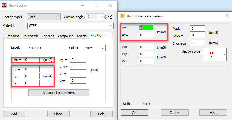
I can multiply with a certain length to remove the per meter, but after that, where should I place the 3 properties of the beams? I am guessing in one of the red boxes Ive highlighted below since the units coincide, but which ones would it be?
1_nb8wtr.jpg
 
Replies continue below

Recommended for you

You need to assume something and then back calculate the other values so that you get the section properties that result in the effective section properties you have been given.

For example if bending stiffness per length is defined as EI, you would either need to know or assume one of these properties and then solve for the other.


For example if you assume E and solve for I this element would provide a consistent beam deflection but the peak bending stress would be completely fictional, so if you do something like this use ample caution.
Understanding how section properties impact FEA results for stress and deflection is absolutely necessary in order to do this.
 
This looks like Robot - look at the documentation that defines their notation for the various stiffness's.

the shear stiffness is likely defined in the material rather than the section.
 
I dont need all the properties defined for the beam element, only the three Ive been given (Iy, It, Az):

1_uw4w6v.jpg


This is from documentation:

Ax= cross sectional area
Ix= torsional moment of inertia
Iy= Bending moment of inertia around local Y axis , usually the greater moment of inertia
Iz= Bending moment of inertia around local Z axis , usually the smaller moment of inertia
Ay= shear area on Y local direction
Az= shear area on Z local direction

Could it be that Iy = I_y (Robot), Az = Az (Robot), and I_t = Iz?
 
You should also look at the Robot definitions of element local axes.

Do you know what material the element is and does it have an established modulus of elasticity ? If it does you can Just solve for the moment of inertias that you need (primary bending and torsional) for shear you will want so see how robot handles it, good chance you need to include the shear area and the shear modulus (Poisson's ratio relates to E modulus for isotropic material).
 
if you can't read the manual, of follow the exmaples, then play with the code. put in numbers and change them until you understand what they do.

Some look "obvious" ...

Ax = cross sectional area
Ix and Iy would be 2nd moments of area about the x and y axes (however these are defined).
one could be zero if an axis of symmetry exists.
Iz = Ix +Iy (assuming x and y and the in-plane axes).

oh, I've read your later post ... x is out-of-plane and y and z are in-plane. "odd" but ok, it's a definition.

to say Iy is usually larger than Iz is "odd". y- and z- are the two in-plane directions and should obey the RH rule.

"Ay" and "Az" look odd ... like sections thru the beam (hence length plays a part). No idea what they mean !!?? but maybe you don't need to define them.

Still you should know what the program does with zero.

"Hoffen wir mal, dass alles gut geht !"
General Paulus, Nov 1942, outside Stalingrad after the launch of Operation Uranus.
 
Status
Not open for further replies.

Part and Inventory Search

Sponsor