Continue to Site

Eng-Tips is the largest engineering community on the Internet

Intelligent Work Forums for Engineering Professionals

  • Congratulations GregLocock on being selected by the Eng-Tips community for having the most helpful posts in the forums last week. Way to Go!

Special Moment Frame Base Anchorage to 18" Concrete Wall

Status
Not open for further replies.

cal91

Structural
Apr 18, 2016
294
I have a W21X201 column with 12,100 k-in and 230 k uplift to anchor to the top of an 18" 4000psi concrete wall.

I'm trying to find the minimum embed to satisfy concrete break out per ACI 318-14 17.4.2, however I'm a little lost because If I calculate Anc as 18" * 3*Hef, I get that I need 1,200 FEET of embedment.

If I just assume ANC/ANCO = 1.0, and I modify equation 17.4.2.2a by replacing hef^1.5 with hef^0.75, to account for my cone being one dimensional not two dimensional, I get I need 12 feet of embedment which seems high but is atleast in the ballpark. However, I never used the 18" wall thickness to determine that, and I know it's not the right way to do it. However, none of the examples in Figure R17.4.2.1 show opposite sides having limiting edge distances, and 17.4.2.3 is only for having 3 sides being limiting edge distances. Why can't I find any provisions for opposite sides having limiting edge distances?

Thanks
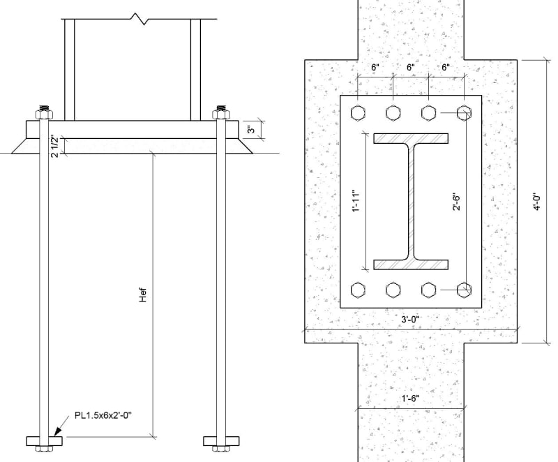
Capture_mlrpsv.jpg
 
Replies continue below

Recommended for you

Another logical method is to treat the concrete wall as a concrete beam of depth, Hef, and make sure that the shear strength of the 'beam' is sufficient.

So the tension anchor rods would be resisting 12,100/ 30" + 230/2 = 518 kips. The 'beam' shear would be 518/2 = 259 kips.

Using Equation 22.5.1.2, Vu = 259,000lb = 0.75* (10 * sqrt(4000) * 18" * Hef)

Solving for Hef gets me 30.3" embedment.

I feel comfortable using this for my calculations and specifying 36" embedment, but I'd love to hear from you guys
 
ACI 318-14 17.4.2.9, covers the condition if you cannot get concrete breakout to work. Additionally your Ano/Anoc will not be 1.0 you are cutting off a large chunk of the concrete which you are counting on. You are also going to have issues with side-face blowout with the loading to the anchors. You dont mention the load comb. used for the moment and uplift, but the simplified assumption you made for the moment arm is not correct, a more detailed analysis will yield higher tension loads.
 
sandman, but I should be ABLE to get concrete break out to work, I can embed my anchors up to 20'-0" if I need, and there is plenty of wall to grab. However, the provisions seem to be way to conservative for this case. The strength of the concrete break out is proportional to the square root of my embedment. (To double my strength I need to quadruple my embedment depth).

And i know Ano/Anoc is not 1.0. I was taking it as unity because I was 'taking the hit' by using hef^0.75 instead of hef^1.5 in equation 17.4.2.2a just for a gut check.
 
Well several problems, a 20'-0" anchor exceeds the maximum 25" hef would can use per Ch. 17 and it would likely still fail when you account for edge effects. ACI has several sections covering using anchor reinforcement, diagrams and additional resources. I would look into those before continuing the design.
 
I noticed Hilti limits embedment to 25". I don't see why (I'm not very experienced in concrete or anchorage design). Am I incorrect in that you would use equation 17.5.2.2b only for 11<=hef<=25, and you use equation 17.4.2.2a in all other cases? I see nothing saying that you cannot use equation 17.4.2.2a for hef >25.
 
The paper "Design of Anchor Reinforcement in Concrete Pedestals" by Widianto et al is a helpful resource for pedestal anchor reinforcement design. Just search for it with google.
 
cal91

First, Acn/Acno can not be simply increased to 1.0. This is serious. Do NOT do it. Almost every factor other than Acn/Acno can be somehow justified, as long as you follow all kinds of test report, but not Acn/Acno. This is a factor representing the actual effective area to theoretical area. Don't do it.

Like samdman21 said, anchor reinforcement seems the only way out for you. However, I don't think a solution like 14#9 under each side of anchors for this "thin" wall will make you comfortable.

sandman21

I'm also curious where I can find that 25" limitation. Could you point out which version and which page of ACI you are referring?
Thanks.
 
Just to clarify: I was not ever going to use Acn/Acno =1 as my actual "calculation". I was just trying to get an estimate of how much embedment I would need while in the meantime trying to find the "correct" solution. Because I really don't think that I need 1200 FEET (!!!) of embedment.

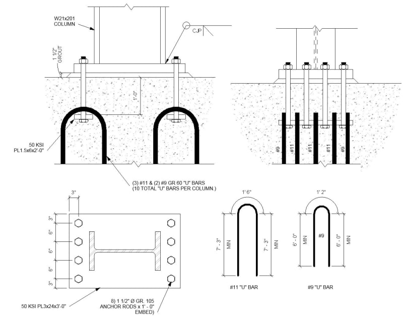
Here's a question: If embedding my anchors 12'-0" isn't working, then why does embedding them 2'-0" and then using anchor reinforcement developing over 10'-0" okay" Is it because the anchors have a point load to the concrete at the bottom of the embedment, while the anchors are a distributed load over their entire development length?
 
Ended up just going with rebar. At first I didn't see any point in providing rebar instead of just embedding the anchors deeper.

But after mulling it over I think I understand the benefit of the "distributed load" to the concrete that the rebar provides, rather than the concentrated load that a headed anchor provides.

Thanks all!

And if you see any issues feel free to critique! (I purposefully am not stiffening the baseplate, the anchors are designed for the maximum force the baseplate can deliver)

Capture_vjie5x.jpg
 
CAL91 said:
Here's a question: If embedding my anchors 12'-0" isn't working, then why does embedding them 2'-0" and then using anchor reinforcement developing over 10'-0" okay"

Embedding your anchors 12' would work, it just wouldn't be "anchorage" design any longer in the conventional, appendix D sense of it. Rather, you'd be doing reinforced concrete design with the anchor rods as your reinforcement. It's a gloriously direct load path really. The only stumbling block, particularly in jurisdictions where most things need to be justified by testing, is justifying the development/anchorage on something that is neither conventional rebar nor end anchorage. Unless you do some serious sleeving etc, I'd be pretty skeptical of an end anchorage 12' below the base plate. In the past, I've used threadbar this way. It's been a while so I don't remember the exact details but I do recall digging out the spec on rebar threads and then making the case that the threadbar deformations would exhibit better development characteristics than conventional rebar.

I'm not a fan of your latest. It seems to me that you're relying on a difficult to quantify mechanical connection between the anchor plate and hairpins rather than doing true RC concrete design where you would pass the force from anchor plate, to concrete, to rebar, dealing with all of the little detailing idiosyncrasies along the way. In the ultimate condition, I also think that this scheme would invite a lot of strain in the connection. Like Bones, I recommend the Widianto approach. Or a hybrid between that and classic AISC design guide #1 procedures. Essentially, you'll simply extend your anchors far enough that a plausible concrete breakout surface coming up from your anchorage leaves your adjacent rebar developed above the crack plane.

Do you have a monster shear to deal with here too?

I like to debate structural engineering theory -- a lot. If I challenge you on something, know that I'm doing so because I respect your opinion enough to either change it or adopt it.
 
As the commentary for 17.4.2.2 states using 17.5.2.2b for embeds greater than 25" could be unconservative, previous editions had 25" as a hard cap on embed, so I was incorrect about the limit. The idea about using anchor reinforcing to take your breakout is not to embed 25" and add some bars. It is to provide an assembly that will effective transfer loads from anchor to concrete and concrete to reinforcing. Think about it this way if your anchors were reinforcing how far would you lap with the bars? 25"? 30"? If I were designing the connection the column would be embedded into the column with suffiecent reinforcing to transfer moment, shear and uplift.

Edit: To address Kootk comment, if they are designing per AISC 341, the greater of shear strength of column or overstrength shear. Likely somewhere in the 200k range
 
A couple comments:

can you hook #9 and #11 bars that tight? check CSRI.

the U bars must be fully developed in the break out cone for the anchors. your detail does not look to have enough engagement. If you can justify it, make sure the concrete stress between the U bar and the plate at the bottom of the anchors isn't too high.
 
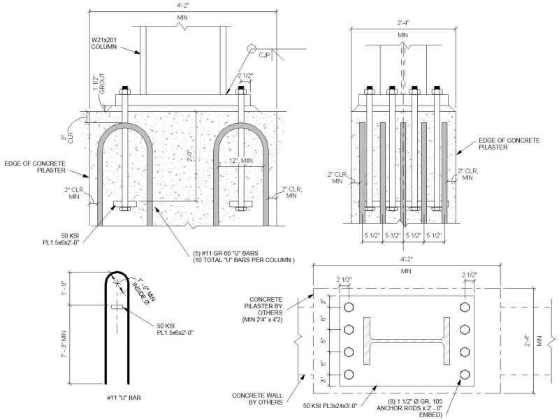
I would recommend using the vertical pier bars as the anchor reinforcement for tension breakout, with an appropriate amount of lateral ties. This approach uses a combination of rebar development and strut-and-tie concepts. It's a rational way to justify the capacity of standard detailing practices for concrete piers. The detail you are proposing is pretty non-standard.

If you can't achieve Ld of the vertical pier bars above the breakout cone, you could hook them or use Lenton terminators. You could always use more bars of smaller diameter, since they will have shorter development lengths.

 
Use the equations - get 1,200 ft. long anchor. Heh.

ACI_T-SHIRT_moyxxf.jpg


Check out Eng-Tips Forum's Policies here:
faq731-376
 
I saw a detail on some transmission towers where they extended the vertical rebar up and out of the pier, then threaded it to create the anchor rods. No laps to worry about.

BTW - the out-to-out on a 180 hook #11 bar is 14.75".
 
KootK said:
I'm not a fan of your latest. It seems to me that you're relying on a difficult to quantify mechanical connection between the anchor plate and hairpins

I was thinking, much like shear anchors with hairpin reinforcing (see ACI Fig. R17.5.2.9a), I could rely on the "mechanical connection". You convinced me to look into this more and ACI doesn't suggest doing this for bars greater than #6, because the large bend radius may significantly reduce the effectiveness of the anchor reinforcement (see ACI R17.5.2.9)

This does make me wonder, however, why I never see this "hairpin" reinforcing for tension anchors like I had shown on my latest update, even for bars #6 and smaller? It seems more direct, uses less space, and seems easier to install. Anyways, I need larger than #6 so I changed the detail.

KootK said:
Do you have a monster shear to deal with here too?

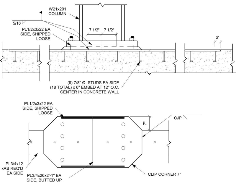
Is 278 kips monstrous? I'm showing my shear anchoring in another detail to not clutter. Feel free to critque.


Here's my latest.

Capture_zt5uoq.jpg

Capture_bvjmpt.jpg
 
cal91 said:
I'm not very experienced in concrete or anchorage design

cal91 said:
Is 278 kips monstrous?

Ok, no offense, but these ARE what I would consider monster loads being transferred from a column into the top of a relatively thin wall, and this design should be done under the supervision of someone with plenty of experience doing similar designs. Whatever your final design is, I hope you will have someone more experienced in concrete and anchorage design reviewing it for you.

Do you have any lateral ties enclosing the anchors/hairpins?
 
Status
Not open for further replies.

Part and Inventory Search

Sponsor