Continue to Site

Eng-Tips is the largest engineering community on the Internet

Intelligent Work Forums for Engineering Professionals

  • Congratulations KootK on being selected by the Eng-Tips community for having the most helpful posts in the forums last week. Way to Go!

Specifying a basic angular dimension when it is a repeating decimal 2

Status
Not open for further replies.

BradVanasse

Mechanical
Jun 19, 2006
10
I am wondering how best to specify a basic angle when it is a repeating decimal. I don't want the cumulative effect to be out of tolerance and the number of repeats is significant. In this case, the angle is 360 deg / 105 and there are 103 repetitions. It's a series of features repeated almost but not quite all the way around, so I can't use, "105X EQUALLY SPACED BASIC." Should I use, "103X [360 DEG/105] (3.429 DEG)," or, "103 PLACES, 360 DEG/105 BASIC, (3.429 DEG)"? (The intent of including the reference angle is to reduce ambiguity.)
 
Replies continue below

Recommended for you

Basic dimensions are no subject to cumulative effect, so [105 X 3.429 deg = 360] should cover it.

"For every expert there is an equal and opposite expert"
Arthur C. Clarke Profiles of the future

 
I think your "103X [360 DEG/105] (3.429 DEG)" is probably the best EXACT option although 103X [3.42857] is probably close enough for all practical purposes.

----------------------------------------

The Help for this program was created in Windows Help format, which depends on a feature that isn't included in this version of Windows.
 
CheckerHater, I understand that Basic dimensions are not subject to cumulative effect, but the expression "3.429 DEG" is an *approximation* of the theoretically perfect dimension. How does the reader know that the theoretically perfect value of 3.428571 (with the decimal part repeating ad infinitum) is meant and not merely 3.429? Is that why you included "= 360"? Is that the standard way to handle this issue? I haven't been able to find it in ASME Y14.5M-2009. (Incidentally, your equality is mathematically the same as mine.)

Also, how would you suggest that I indicate that there are only 103 feature repeats (102 spaces), with a 10.2857 DEG gap between the first and last?
 
dgallup, I agree that [3.42857] is close enough. I was getting hung up on the "Basic = theoretically perfect" definition. I guess what I was really searching for was whether there was an accepted standard way of handling the issue. It sure seems like it would have come up before.
 
BradVanasse,

ASME Y14.5-2009 Fig. 7.30 shows a basic angular dimension expressed as a fraction. No decimal approximation is provided. That's the approach I'd recommend if you can duplicate the formatting.

If you express the basic dimension as a decimal value on the drawing, you should probably use that same decimal value in your model to avoid unnecessary rounding.


pylfrm
 
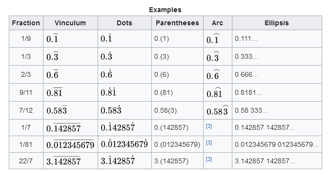
Would it be acceptable to use one of the standard Mathematical notations for a recurring decimal:

examples_hq3003.png
 
Rothers - The fact that your chart shows 5 different ways to show recurring decimals points out that in fact there is no standard way to show recurring decimals. Some of those are rather obscure, I've never seen the dot method before. Also, I think it could be somewhat difficult to get various CAD systems to display a dimension that way.

----------------------------------------

The Help for this program was created in Windows Help format, which depends on a feature that isn't included in this version of Windows.
 
Everything in the GDT world that is perfect must be simulated by processing equipment - mfg and inspection. The number of decimal places expressed in the BSC dimension is an indictor of the precision required for the part to function as intended. The accuracy/repeatability of processing equipment must be better than the stated precision – usually in the next decimal place for rounding and measurement error to be accommodated. Just my two cents.

Certified Sr. GD&T Professional
 
I would say the precision of the equipment needs to be based on the extent of the tolerance zone and that any increase in the number of places is only significant if the part is encroaching on the limits of the zone. So if I had a zone that was 1 inch in width and the part was nominally near the halfway point, that a tolerance of +/-0.25 inch on the measuring equipment would be acceptable as long as the inspection limit was reduced to 0.5 inch. Increased inspection precision expands the inspection limit to be closer to the tolerance limit, so if the part was produced to 0.999999999 and it's desired to be sure, then the inspection equipment must be more precise than that.

The typical 10% rule is fine for gathering statistical data; it isn't needed to accept the parts.
 
3DDave;

I agree with your statements. And yes, as the error approaches the limits of the tolerances measurement error get attention!

Certified Sr. GD&T Professional
 
Accuracy of the measurement system is a function of the tolerance required, not the number of decimal places in the nominal value. Nowhere in this thread has anyone stated the tolerance of the measurement.

----------------------------------------

The Help for this program was created in Windows Help format, which depends on a feature that isn't included in this version of Windows.
 
dgallup:
The OP was asking about BSC dimensions. I was trying to communicate my understanding of what determine the precision/accuracy of the true position location defined by perfect BSC dimensions, and not the precision of the measurements taken to confirm the features’ actual position error is with the tolerance zone (located at true position).

For example: the movement of a machine tool (processing equipment) simulates the “perfect” BSC dimensions. What determines the precision required for the movement(s) of the machine tool? The OP stated “3.429 DEG” - this is a rounding of 360/105 to three digits. Per Y14.5-2018 para 5.3.2 d), the number of significant digits in the BSC dimension indicates the precision required.

So are significant digits (rounding) important to the defining the precision of the machine tool movement that simulates the BSC dimension – an angle in the OP question? I have often wrestled with this perfect vs simulated issue – when is the precision of the simulated good enough to meet the perfection. I guess am trying to apply the principles for perfect vs simulated datums in paragraph 7.6 (in 2018) to BSC dimensions.

This discussion may be a new Post. Comments please.


Certified Sr. GD&T Professional
 
pylfrm, that is what I was looking for. Thank you for the ASME Y14.5-2009 reference. I think I can do this with some creative formating. I suppose that if I have a situation where one angle between two features is different, like say a clock with a missing "12", I could dimension the angle between the "11" and "1" and show the other features as "10X EQUALLY SPACED" with either a box around it or "BASIC" added to it.
 
Status
Not open for further replies.

Part and Inventory Search

Sponsor