Lonjevity Farms
Agricultural
- Jan 2, 2017
- 10
Hello forum, this is my first post and wanted to run a design by you heavy thinkers. I am working to improve our 3 point spider cultivator and want to weld up a pair of casters to mount on it. The implement weighs approximately 3000 lbs. and mounts to the 3 point hitch of our tractor. I have the arm design worked out but wanted some input on the pivot section. Looking at zero turn mower pivot tubes as an example, they typically use bushings and/or bearing combinations. Do you think that this product would work with a 1 1/4" shaft pressed fit into schedule 80 tube? These bushings have quite a large dynamic load capacity.
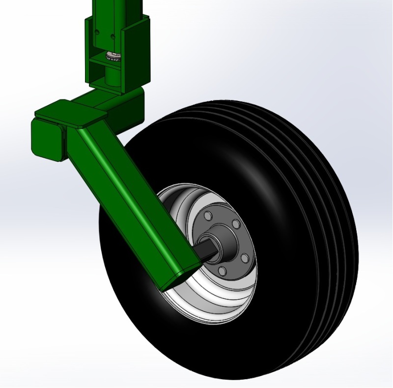
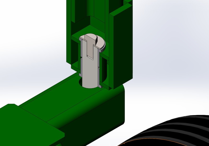
I have attached a few pics of the design from Solidworks. The square tubing is 3 x 3 x 1/4 wall A36 and the shaft is 1 1/4" CR 1020 steel. The pivot tube is X Strong Sch 80 1 1/2" x 1 3/4" long pipe to press the bushings and shaft into. The shaft has a 1/2-20 tapped end for the bolt to apply the necessary preload. The shaft is welded to the square tube via a through hole. The hub and spindle are rated for 1750lbs, two casters total 3500 lbs capacity. Not being familiar with typical tapered roller bearing applications do manufacturers machine out the pivot tube for the bearings or use stock material and press fit?
I could also use these as well but there is significant price difference versus the bushings. Also from a maintenance point the bushings seem a better fit.

Overview image of caster design

Cross section of end bolt, shaft, pivot tube, and bushings; one on top and one on bottom.

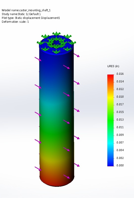
FEM of caster shaft showing displacement. von Mises stress is well within FOS.
Thank you for any suggestions or information.
I have attached a few pics of the design from Solidworks. The square tubing is 3 x 3 x 1/4 wall A36 and the shaft is 1 1/4" CR 1020 steel. The pivot tube is X Strong Sch 80 1 1/2" x 1 3/4" long pipe to press the bushings and shaft into. The shaft has a 1/2-20 tapped end for the bolt to apply the necessary preload. The shaft is welded to the square tube via a through hole. The hub and spindle are rated for 1750lbs, two casters total 3500 lbs capacity. Not being familiar with typical tapered roller bearing applications do manufacturers machine out the pivot tube for the bearings or use stock material and press fit?
I could also use these as well but there is significant price difference versus the bushings. Also from a maintenance point the bushings seem a better fit.

Overview image of caster design

Cross section of end bolt, shaft, pivot tube, and bushings; one on top and one on bottom.

FEM of caster shaft showing displacement. von Mises stress is well within FOS.
Thank you for any suggestions or information.
