Continue to Site

Eng-Tips is the largest engineering community on the Internet

Intelligent Work Forums for Engineering Professionals

  • Congratulations SSS148 on being selected by the Eng-Tips community for having the most helpful posts in the forums last week. Way to Go!

Spliced Beam Reactions 1

Status
Not open for further replies.

Trillers

Civil/Environmental
Feb 14, 2011
66
Greetings:

I am designing a steel beam to support a 16" waterline crossing over a creek. The waterline will be supported by the I-Beam by hangers at 8' OC which I analyzed both ways - point loads and uniform load. The clear span is 72 ft. Because of limited space the contractor can only bring in a maximum 40' length beam so bolted splices will be required. I do not want to use a welded splice as I am not confident that the contractor's welder, although certified can provide the welds we need.

The bolted splices will carry 75% of the beam capacity as per my design. These splices are located at the 1/3 points from each end so the sections between supports are 16'-40'-16'. This was to avoid a splice at the mid-point of the spliced beam. In designing this beam I assumed that the splices can be considered as supports so that the max span under consideration is the middle 40' with the 16' sections at each end.

I referred to AISC Appendix J and the FHWA splice manual. My in-house peer reviewer says he does not believe my assumption is correct, but he does admit he has never designed or been involved in anything like this. I've designed for bridges and structures but never a waterline support, although I believe the principles are the same. Now he has me wondering if my assumption is correct.

Was hoping you structural gurus could chime in? Would hate to have a watermain rupture because of wrong assumptions!!

Thanks!!
 
Replies continue below

Recommended for you

Your first paragraph states that the clear span is 72’, then in your second paragraph you state what appears to be a 3-span beam of 16’ 40’ and 16’ spans.

Are the proposed splice locations also where there will be vertical supports?
 

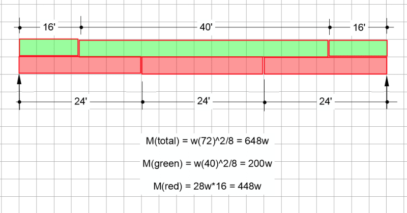
If the span 72' , and the splices are located at the 1/3 points from each end , the sections will be =24'+ 24'+24'.
If the sections 16'-40'-16', and for the assumption of the splices can be considered as supports can be valid if the splice locations are vertical supported , or the 72' span has fixed supports and the splices at 16' are shear connection.( in this case, the 16' sections will be cantilever ).

If the clear span 72' , you shall calculate the effects for this span and check the situation also at splice locations for reduced capacity.

What is the pipeline material and type of joint ? How did you consider the wind effects ?

A sketch and more specific info will be helpful for specific responds.
 
Trillers said:
In designing this beam I assumed that the splices can be considered as supports so that the max span under consideration is the middle 40' with the 16' sections at each end.
What sort of supports? Vertical supports? Lateral supports? Rotational supports?

Please elaborate on what type of support you are considering here because most people reading this are wondering what sort of magic you can perform that enables a splice mid way along a beam to function as a 'support'.
 
The splice is there to stitch the beam segments together to be a whole. It can be a moment, or shear connection, but it's not a support point, as all forces are internal, unless you are going to provide external support, like piers. Otherwise, you have 72' design span, no matter the beam is made out of segments or not.
 
and the splices are transferring the internal moments and shears (in case it wasn't obvious from the previous post).

another day in paradise, or is paradise one day closer ?
 
I usually use something like the attached (from an SMath program):

Conn-Moment_End_Plate__6_Bolt_edoupv.png


Dik
 
This also must be a pretty serious beam if it is a single beam spanning 72' with no bracing. Has lateral torsional buckling been considered? The comment of 75% capacity at the splices is unclear if its the LTB capacity of the beam, or braced capacity of the beam.

As other have said, I would not consider the splices as a type of brace or 'support'. unbraced length would be the full length unless you have other means to brace the member.
 
I have seen 3D truss been used, but much less than 72'.
 
Have you considered snow load and also the inevitable gang of kids using it as a bridge?

At 72 feet you’ll need to be well on top of your deflection control. What is the allowable deflection of the pipe?

Lateral torsional buckling will likely kill the idea of a single beam in any event. This requires due consideration from a structural engineer.

Also - Agree with others above. I have no idea why you would consider a splice as a support? What stops it falling to the ground? Your span is 72 ft regardless from the description above.
 
Just a reminder, ice and corrosion prevention are also to be considered, as the beam is across the waterway. I guess you might need a middle pier (2-36' spans), otherwise, the structure will be huge, and the design of beam end supports would be very difficult.
 
"In designing this beam I assumed that the splices can be considered as support" … NO (as I think we've all said)

you could say that the central (40') section is doubly cantilevered and so distributes it's distributed load to the outer spans as SF and BM, but this would be misleading.

the spliced beam is a single beam (unless there are real supports we don't know about). The applied loads are reacted (to the rest of the world) at the two ends. This means the SF and BM of the central section is not a doubly cantilever beam in isolation, the internal loads on the central portion are increased because out the outer spans.

Your reviewer is correct.

another day in paradise, or is paradise one day closer ?
 
16in dia water pipe, 72' span … 100 ft^3 = 6230 lbs of water (alone)
max moment, assuming doubly cantilevered, UDL = 87 lb/ft, moment = 56368 ft.lbs … conservative SS beam doubles this to 113000 ft.lbs.


another day in paradise, or is paradise one day closer ?
 
Trillers said:
The bolted splices will carry 75% of the beam capacity as per my design. These splices are located at the 1/3 points from each end so the sections between supports are 16'-40'-16'.

Try as I might, I cannot make sense out of the above. Would you mind clarifying what is meant? A sketch might help.

BA
 
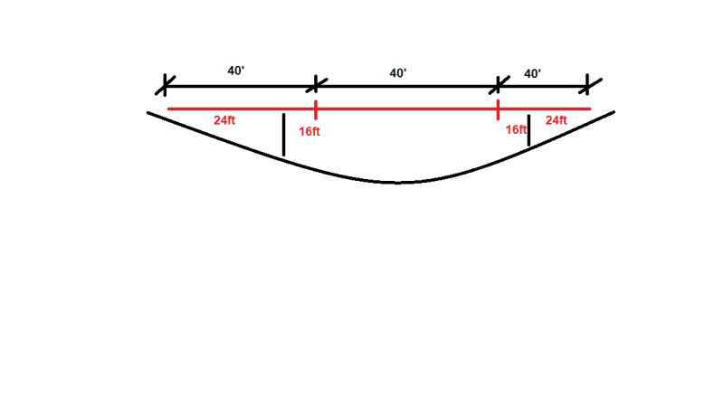
I'm not the OP, but the only way to make sense of this is that the total crossing length is 120 feet between abutments with 72ft between supports. If that's the case, then from abutment to first support is 40'-16'=24'. The first beam cantilevers off this support - 16' canti with 24' back span. Mirror this arrangement on the other side. Then in the middle, we have a 40' stick supported by the two cantilevers.

If this is the case, then you're good to go. Design the middle as a simple span, provide shear connections only, and apply the end reactions to the end of the cantilevers.

crossing_guess_mo2wtw.png
 
Good guess, phamENG. Seems simple enough. I wonder why the reviewer didn't like that. It would be nice to have your sketch confirmed by the OP, who seems to have taken a leave of absence.

BA
 
dik, that is a great reference - just wanted to note that reference doesn't cover a stiffness check. With (2) of these splices in the span I'd want that splice fairly stiff - or at least take a closer look at the effect of a "softer" splice at that location. I think I'd prefer a flange plate splice in this scenario, if forced into the end plate splice I wouldn't feel bad about bumping the end plate thickness up a bit from the minimum required for strength.
 
Canpro... I've always been partial to stiffened end plate connections.

Dik
 
Status
Not open for further replies.

Part and Inventory Search

Sponsor