Eng-Tips is the largest engineering community on the Internet

Intelligent Work Forums for Engineering Professionals

  • Congratulations waross on being selected by the Eng-Tips community for having the most helpful posts in the forums last week. Way to Go!

Splined Shaft Coupling Issues 8

Status
Not open for further replies.

TugboatEng

Marine/Ocean
Nov 1, 2015
11,388
US
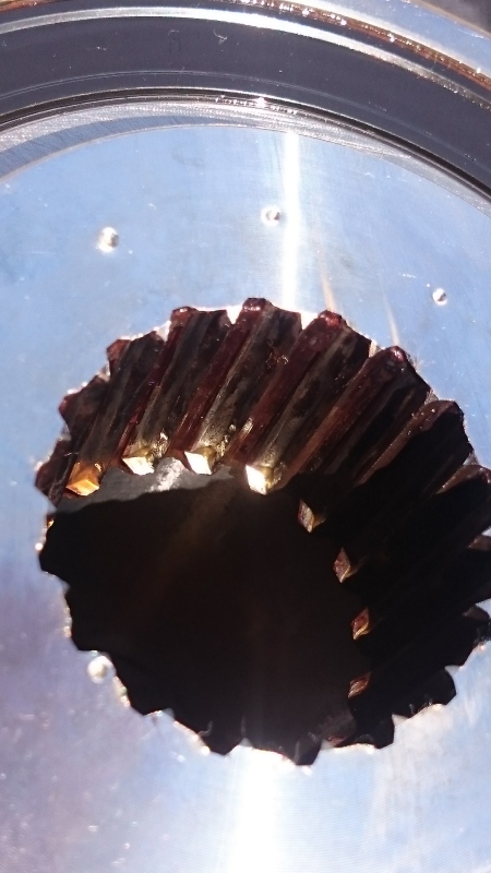
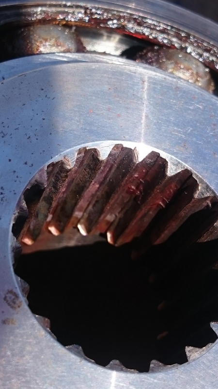
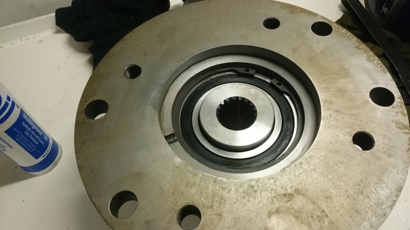
I am having repeat failures of a splined coupling. The system consists of belts and a pulley driving a splined input hydraulic pump through an adapter that is flanged on one end for the pulley and female splined on the opposite for the pump. The splines keep fretting away to nothing. The system came packed with a moly paste type lubricant that quickly gets hammered out of the connection. We switched to an EP grease which quickly gets centrifuged into base oil and thickener. We tried a gear coupling grease, Kop-Flex KSG, which was too thin and passed through the coupling too quickly. There are no seals. We have settled on Mobilgrease 28 which has enough viscosity to stay in the coupling and is stabil enough to make it to a reasonable lubrication interval. We are still getting some random failures here and there, though.

One thing I have noticed is that the female spline is not hardened. A center punch leaves an indentation similar to A36 steel. We are thinking about making our own adapters and matching the hardness of the pump shaft.

However, I have seen that it might be possible to use an anaerobic adhesive to make the coupling rigid and eliminate fretting corrosion. I am interested in pursuing this route and just wanted to see if there was any experience with it here.
 
Replies continue below

Recommended for you

Is this a power take-off from a diesel engine? If yes, then you may have a torsional resonance.

Walt
 
DSC_1967_sog9qp.jpg

DSC_1968_oitmdo.jpg

DSC_1969_wdhi2a.jpg

DSC_1970_gxnkhf.jpg
 
Hi,
i don't know how much you are involved in the design of that splined connection. Also, i don't see the overall picture of the drive train, so assuming from some keywords (pulley, fretting, hammering) imo there's some design checking to be done, notably:
- Were radial force loads correctly considered as well as the pure torque loading?
- Did design decisions consider momentary overload situations, shorttime peaks, sudden load changes (if applicable), change of load direction?
- Are centering, alignment, tooth pressure within spec. / design standard requ.-mts?

These spline connections are quite a good loadtransmitting element, if male/female come together w/o play ("centering"), if axial alignment of male/female is within spec. and if load distribution allows a sufficient number of teeth to share the load.
Lube should not be the issue, imo the moly paste originally applied was to facilitate disassembly. Male / female should not move, let alone fret constantly.
Material might be a part of the case, that again is a design issue.

Regards


Roland Heilmann
Lpz FRG
 
Hi

My ten penny worth, find out why the are failing first rather than experimenting with solutions with unknown results its cheaper in the long run.

What torque and or is the coupling transmitting? Quite recently I went to look at some screw jacks that kept failing so I did some basic calculations based on information from the manufacturer and found they were overloading the jacks beyond the recommended rating.

“Do not worry about your problems with mathematics, I assure you mine are far greater.” Albert Einstein
 
No, I had nothing to do with the design process, I am an end user. We have come up with solutions for most of the little problems we see on these drives but this one keeps coming back. The manufacturer appears to have changed from moly paste to some kind of grease for lube but that is all. I was trying to avoid spilling the beans on what the equipment is but..

*pictures removed to protect identity of manufacturer*
 
There are many types of splines, can you easily remove the spline hub for service or is heat required?

The main advantage of a spline is that is transmits torque very efficiently and self centers the transmitting components yet allows for easy removal and service. The only real downside is that they are costly to manufacture.

Where traditional clearance fit splines are not good is when you put a belt on it, to drive torque via a side loading condition. This mitigates the primary advantage of the spline, its self centering ability. It also creates a binding wear condition where the spline will continue to grind away on itself because the male and female components are off center due to the side load of the belt and pulley system.

What you need a major diameter fit spline, or and interference fit hub. Unfortunately this will render its other primary advantage useless, its "easy removal."

A compromise would be a taper fit hub, which can give you some easy service ability but not as easy as a clearance fit spline.

What makes the problem even worse is that you are dealing with a vibratory torque input, looks like you are dealing with a slight design flaw, but I am sure it can be corrected.

When it comes to couplings we are always here to help.
 
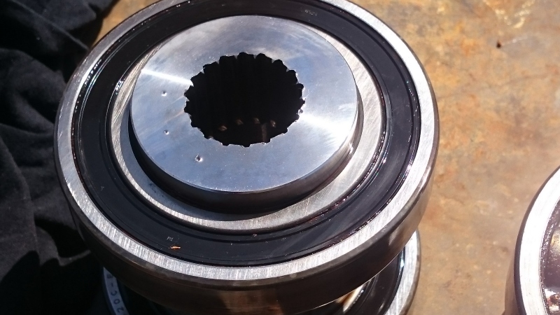
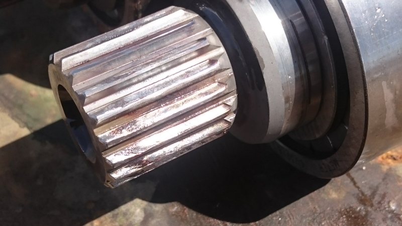
There is a driver which is supported by two deep groove ball bearings between the pump shaft and pulley.

DSC_1869_a98okf.jpg

DSC_1871_ucngc2.jpg
 
If I am understanding what I am seeing, the manufacturer has done an amazing job restricting the movement of the splined connection, being that the hub is supported by 2 generous bearings. But a clearance fit splined connection should be allowed to find "home". With this current set-up that will require the run-out of that spline to the bearing surface to be perfectly controlled, even a few thousanths run-out will grind the spline away rapidly, any ideas on how to check that spline run-out to those bearings?

On a side note, I think they already knew they had a problem, it seems highly over-designed.

When it comes to couplings we are always here to help.
 
I see the two radial bearings that carry the radial load from the belt, so I can't see a change in spline form as helpful.
I'm assuming that the olive drab colored adapter shell is fairly stiff, and equipped with a pilot for the hydraulic pump, so misalignment or mispositioning of the shaft vs the hub is likely not a problem.

Which leaves hardening of the female splines. I doubt that an experienced manufacturer would forget to do that, though a manufacturer's Supply Chain Manager might eliminate the process step in order to 'save time'.

I suggest you have some hubs made with hardened internal splines, or find a coupling hub with hardened splines and get a machinist to join the splines from the hard hub with the remainder of the OEM hub, with Dutch pins or other keying scheme.


Mike Halloran
Pembroke Pines, FL, USA
 
As usual Mike is making some great points, only concern with that solution is that if there is a design induced run-out problem, then that could just transfer the problem to the bearings.
When it comes to spline failures, typically the hardest surface wins. I caution the conclusion that it is a hardening problem, maybe on a one or two case basis, but continually? either way it is easy to rule out, so I agree with Mike just verify that if you haven't already.

When it comes to couplings we are always here to help.
 
We're willing to make a whole new driver. Is there any preferred steel for female splines? 1040 or something with some alloy?

I will see about getting the driver hardness tested. In 10 years we have gone though close to 10 of these. They're all soft when punched with a center punch. Would there ever be a reason to make a spline soft?

For the running clearance, the pump does fit the green colored housing with a register. Some of the bearings have spun in the housing resulting wear to the housing. The wear becomes obvious as it causes uneven tension of the 6 drive belts. The housing wear is on the magnitude of 0.015mm by the time we see changes in belt alignment. The nominal size is 130mm. We have not seen any change in spline wear rate in the worn housings. I am having the worn housings hard chromed to restore the ID. I have specified an H7 fit for the repaired housing.
 
Typically a splines function is not to be like a gear, there should be very little movement in the spline when it is under torque, so in most cases when we have seen spline wear it is a symptom of another problem. If you are looking for it to withstand wear, I would recommend an 8620 steel with a carburized spline. Should be able to get that up to RC60 or higher locally at the wear surface. But you may end up just wearing out the external spline component.


When it comes to couplings we are always here to help.
 
Just a little more information, the shaft spline appears to be DIN 5480 40x2x30x18x9g.
The maximum power the unit can draw is about 150 horsepower at 2400 RPM. That is at 3000 psi but the system rarely operates at over 1000 psi.
 
I like the idea of taking the slack out of the spline with Loctite, but that will cause bearing problems unless all the parts are made really well, because then you end up with a short composite shaft having at least three, maybe four, bearings supporting it.

OR unless you provide some lateral flexibility in the composite shaft, e.g. by:
- Making the female spline part of a shaft that extends completely through the bearing-supported sleeve past the timing belt pulley, where the pulley/sleeve and shaft are joined by a radially flexible coupling, or
- the female spline ends in a severely necked down round bar that ends in a flange bolted to the sleeve end, like a full floating truck drive axle. It would all work better if there's quite a bit of axial space on the non-pump end of the drive so that necked down (and spring tempered) shaft can be long enough to allow some misalignment/offset of the various bearings involved.

IF the parts are pretty good, you could just assemble parts to the existing design with some Loctite in the splines, and let the Loctite cure _while_ the drive is running at low load.


Mike Halloran
Pembroke Pines, FL, USA
 
Too bad the OP removed the installation photos so as to not embarrass the guilty.

Working from memory, I'm thinking that if the pump were moved 'aft' a couple of feet, it could be driven by a slightly flexible shaft with male/female splined ends, both ends secured to existing parts with Loctite in the splines.

... at some expense in weight of bracketry, possibly not in cost if you think of the pump/bearing assembly like a pivoting jackshaft and get rid of the machined slide assembly.


Mike Halloran
Pembroke Pines, FL, USA
 
I would lean toward a torsional resonance, but that is hard to discuss and prove in a forum with limited information.

Walt
 
I read the Loctite bit in an old Danfoss article. I think this is a good candidate for it because the two deep groove ball bearings on the driver have a radial I clearance fit in the housing of about 0.0005-0-0015" and about 0.025" of axial clearance. The pump shaft has one cylindrical roller bearing and one plain journal bearing. There is some axial freedom there but it's hard to measure because the shaft is driven forward by a spring. It's at least 0.010"
 
Walt, the belts do vibrate up and down a bit on the loaded side. This could be a sign of some resonance? I will try to make and post a video soon.
 
Status
Not open for further replies.

Part and Inventory Search

Sponsor

Back
Top