Continue to Site

Eng-Tips is the largest engineering community on the Internet

Intelligent Work Forums for Engineering Professionals

  • Congratulations KootK on being selected by the Eng-Tips community for having the most helpful posts in the forums last week. Way to Go!

Split bases of weld on pad-eyes/lifting lugs - Why? 11

Status
Not open for further replies.

Nereth1

Mechanical
Feb 2, 2014
136
For mostly curiosity, but at this stage also the preservation of sanity, there is an ongoing discussion in our office on why we see weld on pad eyes/lifting lugs with splits in them. See image below:
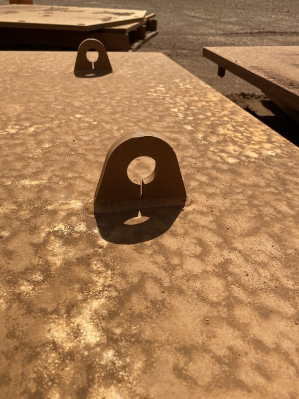
Split_pad_eye_tfwlb6.jpg


We can speculate some minor decrease in certain stresses (e.g. contact stress reduction as it will more easily flex to conform to slightly lower radius of the pin inside it), but at the cost of large stress increases in other areas (bending stress in the eye, peak fatigue stress concentration for any longitudinal stresses in the plate to which it is welded to). It doesn't seem easier to weld (if anything it seems more difficult), and it doesn't seem cheaper to manufacture.

So we are generally at a loss.

My best guess is someone drew this 40 years ago by hand, sneezed near the end of the drawing process, left a line on the drawing, and went "Well, not drawing that again. Guess it's a feature now." and it never got corrected.

But realistically it's across multiple client sites, vendors, and industries. It's not common, but it exists everywhere. So there must be some reason this exists.

Can anyone try to illuminate me a little on this one?
 
Replies continue below

Recommended for you

I think it is meant to distribute the stress more uniformly, and making the pad eye more ductile under ultimate load. A FEM analysis could tell the difference.
 
Yes... can someone tell me... I've never done this before.

Rather than think climate change and the corona virus as science, think of it as the wrath of God. Feel any better?

-Dik
 
I suspect that the split weakens the lug under all load conditions. The originator perhaps intended to eliminate the stresses in the area using u-bolt type lifting. However the diametral difference between pin and hole, angle lifting might be unconsidered, and the concept perhaps used for light lifting only.

In case this application is to be used for high forces and angle lifting a FEA is essential.


Obvious - weight reduction. /s

The only thing that comes to mind is to allow drainage/ensure corrosion induced rust doesn't build up quite so fast, but that's a pretty weak guess. Certainly it is done to prevent some problem, but the rarity among pad-eye makers indicates the problem is also rare.
 
Maybe the same reason some engineers still put nosing bars in concrete stair treads.

Rather than think climate change and the corona virus as science, think of it as the wrath of God. Feel any better?

-Dik
 
Picture is not very clear, but is that weld continuous (eg., leaving a small encased "pool" inbetween both halves), or are the welds cut after welding, or what exactly is going on here?

I have seen (en detailed) a fair share of (welded) lifting lugs, but this is a first for me.
I don't think it distributes the stress more evenly, a full/continuous bottom part of the lug is the best way to distribute the forces over the entire bottom surface.

Quote 3DDave: if they were aiming for weight reducting, the most efficient way is to enlarge the diameter of the hole...
 
It's how you get the jigsaw blade in to start the circle
 
For most cases the lifting eyes or support lugs are removed by cutting and the surface grinded smooth.
However,for some equipments and machines the lugs are permanent and the equipment may be lifted a lot of times during service life.

The lifting lugs may subject to axial, out of plane, and in plane oblique loading more over, the oblique loading could be totally horizontal and shear loading will govern..

One can see the difference with a simple calculation for impact loading. Consider a cantilever beam plate tip impacted . The impact stresses will be less for the slotted cantilever .

IMO, slotting the lifting lugs for temporary cases is not necessary..
 
Thanks for your responses so far guys. The most realistic sounding guess in our office so far, is that it gives a way for the padeye to shrink to relieve welding stresses along its length. For me though, while this would reduce welding stresses... why? If eliminating the stress was to reduce distortion, it probably would not work (since normally the padeyes' longitudinal rigidity prevents deformation along that axis anyway, if anything this gives the substrate a point to 'kink' around), and in terms of fatigue strength where the residual stresses on that axis could be detrimental - I can't see them being less detrimental than the addition of the slot itself.

kingnero said:
Picture is not very clear, but is that weld continuous (eg., leaving a small encased "pool" inbetween both halves), or are the welds cut after welding, or what exactly is going on here?

Weld is continuous.

For the record, this is certainly rare, but, with some google, you can find it in various places:

See another example here.

steveh49 said:
It's how you get the jigsaw blade in to start the circle

Zooming in (I have a higher res image), it's laser cut (which is it's own issue...).

HTURKAK said:
One can see the difference with a simple calculation for impact loading. Consider a cantilever beam plate tip impacted . The impact stresses will be less for the slotted cantilever .

Can you please elaborate on this? I can't see it. Are you literally talking about a reduced stiffness reducing peak forces in impact?

 
I wonder if it's as simple as not turning off the laser, water jet, or whatever other mechanism they're using to fab these. Maximum fabrication efficiency would probably come from arranging a bunch of these on a plate in such a way that it's just one long cut.
 
With some cutting methods, it's harder to penetrate a plate than it is to cut in from the edge, so it's easier to cut it that way than to penetrate it and cut the hole or drill the hole.
 
If that is the reason, that is a bullshit reason to make it like that. They can penetrate in the middle of the circle (this is in a discard zone), so the rough cut/entry hole will not be incorporated in the part.
For lifting lugs, this is not a part where economy should be first priority.
 
I've never, ever seen a lifting lug made like that. And I have a hard time imagining that it makes the lifting lug better in any way. It certainly complicates welding.
 
So the manufacturer uses single tool to make the entire shape without touching it using their cutting methods. İt is cleaver on the manufacturer side for the lug. Welding is a bit problematic, they will have more start and stops, split area may be more [pre][/pre]prone to welding failures.

Loading/design side have some questions that we identified above.

As conclusion this split shape with comes from the lug manufactuer to make life easier for them.
 
Piercing that hole depends on how thick the plate and what method you're using. Normally, in cutting, all the sparks, slag, molten metal, etc, all go flying through the cut and out the backside. On that pierce, until the hole goes through, it all has to blow back up towards the machine and/or operator, so there's a limit on what you can practically do or want to do. If I remember right, there were issues with that clogging up the plasma cutter in some circumstances.
As to design and welding, that would depend on the circumstances. It may be easier to oversize the lugs and cut them that way than to make them smaller without the cut. In some applications, they'll be removed after erection anyway. They could potentially be cut with a large gap instead of a small gap if that was preferable.
 

Yes... your interpretation of my comment is correct . The reduced stiffness also reduces peak forces in impact. The second picture that you posted more prone to impact stresses for bending and shear.

pad_eye_sk7cji.png


Some of the comments are for cutting method .. IMO, penetrating inside the circle which will be discarded, will be more practical.

I just want to remind that the impact force during lifting should not be underestimated. API recommends the use of load factor of 2.0 applied to the calculated static loads for some cases.

I am not defending the slotting of pad eye. IMO, engineering is an art rather than a sicence and local practice will vary. The slide rule engineers may remember, there was an old Japanese technic ; shear walls with vertical slots to improve ductility during a seismic event..
 
I've noticed the street light standards have the anchor locations with a continuous cut to form the holes as part of the base plate... may be a manufacturing item...

Rather than think climate change and the corona virus as science, think of it as the wrath of God. Feel any better?

-Dik
 
HTURKAK said:
Some of the comments are for cutting method .. IMO, penetrating inside the circle which will be discarded, will be more practical.
More practical for who?

JStephen gave a great summary of the cutting process. No one is saying that the manufacturer can't pierce the piece to create the hole if required, just stating what the preferences are and why.
If I am a manufacturer and I know that my equipment can cut the piece with no piercing required, faster and with less wear on the equipment (piercing takes longer and wears the tip of the plasma cutter out faster, especially for thicker steels) that is going to be my preference. If the design engineer allows this, great! If not, I would plan (and charge) accordingly. If the manufacturer is also the designer (or in charge of the design) I can guess which route they would pick.

Back to the original question, the manufacturing process seems to have the biggest advantage/reason for the split.
 
There was a thread here years ago about the light pole baseplate slots that Dik mentioned above. My first thought was the continuous cutting and not needing to 'pierce' for each hole. At least in that case drainage also makes sense.
 
Status
Not open for further replies.

Part and Inventory Search

Sponsor