Continue to Site

Eng-Tips is the largest engineering community on the Internet

Intelligent Work Forums for Engineering Professionals

  • Congratulations MintJulep on being selected by the Eng-Tips community for having the most helpful posts in the forums last week. Way to Go!

Split Phase Motor Connection Help

Status
Not open for further replies.

JMGotts

Electrical
Jul 7, 2024
8
I picked up an old GE 5KCP19 motor and it has a five wire connection. Metering the leads, the continuity values are as follows.

Bk-Wht. 0
Bk & Wht-Red 92
Yel-Blu 17

Motor Ratings…

115V, 1650/1350 RPM, 35 Mhp, Cap 4Mfd. CW/CCW

Would appreciate connection help (simple diagram) so I can use it.
Thanks!
 
 https://files.engineering.com/getfile.aspx?folder=d2110151-f377-49da-9dd2-264c54e86efd&file=IMG_0834.jpeg
Replies continue below

Recommended for you

Oh, sorry, I didn't see the 60/50Hz on there...


" We are all here on earth to help others; what on earth the others are here for I don't know." -- W. H. Auden
 
No problem. I forgot about the small motors with fairly high resistance windings that reduce effective torque to increase slip.
The resistance values seem to be missing something.
Hence the suggestion of a possible meter issue.

--------------------
Ohm's law
Not just a good idea;
It's the LAW!
 
Sorry JMGotts, but your last post and the diagram look a bit confusing.
Besides, you didn't draw the thermal protection that exists in the motor (usually close to zero resistance).
My suggestion is to take the motor to a service center where they can properly test, label, and connect it to power.
ACW
 
Well gentlemen, my puzzle is finally solved...
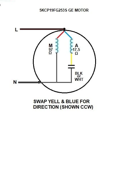
First things first, this is a PSC motor, not split phase, as there is no CF switch.
Here is my final diagram (that works,) both directions and correct torque.
After getting it running correctly, I took it over to the motor shop because I was (and am) confused about the commonality of the black & white leads,
and it doesn't matter if either or both are connected to the cap.
Without testing and just a visual look, he was uncertain as well and explained that usually they go to the source power, so it's still a question.
Additionally, I was quite surprised to see how much torque is applied when the 4MFD cap is installed. Without it in the below config, it spun fast but
could still be stopped with quite a bit of pressure on the shaft.

Anyhow, here's how it's configured to run in both directions. I was able to apply a 3PTT switch for reversing successfully also.
Thanks for all your help and sorry about any confusion from prior posts.

Motor_Connections_seuzxp.jpg
 
No apologizes needed! Glad you got it figured out. Thank you for the follow up / resolve. Hopefully anyone else trying to determine the same will find this thread helpful.
 
In regards to your 10 July post and diagram.
JMGotts said:
Note that the cap is not installed, just running straight wire.
The two windings will be physically displaced the equivalent of 90 electrical degrees.
With the jumper wire, the applied potential will not be displaced 90 degrees.
The two windings will be fighting each other.
It is not surprising that the torque is low.

--------------------
Ohm's law
Not just a good idea;
It's the LAW!
 
Status
Not open for further replies.

Part and Inventory Search

Sponsor