Continue to Site

Eng-Tips is the largest engineering community on the Internet

Intelligent Work Forums for Engineering Professionals

  • Congratulations GregLocock on being selected by the Eng-Tips community for having the most helpful posts in the forums last week. Way to Go!

Splitting the NG Flow between 2 Valves: What will Pressures Be? & Equal to a Maxon Valve? 2

Status
Not open for further replies.

michael333

Mechanical
Jun 15, 2007
20
Hello,

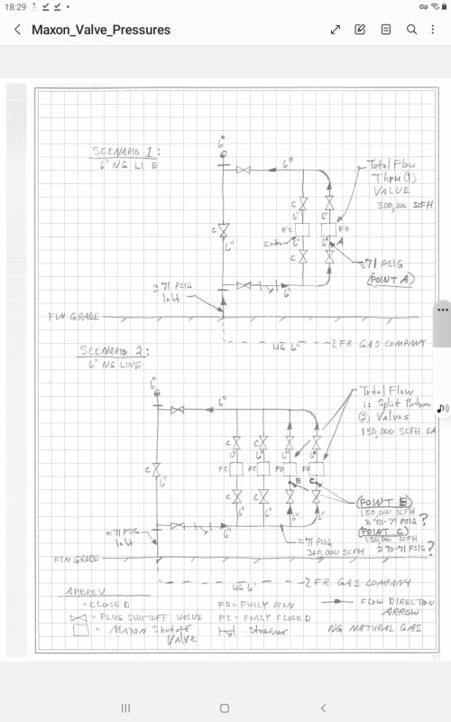
I have an application for natural gas (NG) of Scenarios 1 & 2.
All 6" diameter Sch 40 Carbon Steel piping in the system.
Please see attached Maxon_Valves_Pressures.pdf for your clarity.

Scenario 1:
Have a 6" NG main line coming in from the gas company to a plant via a parallel set of Maxon shutoff valves. 2 total.
(1) Maxon is fully closed, (1) fully open. See attachment.
391,700 SCFH @ 71 PSIG from gas company main incoming line.
NG total flow at "Point A" will be 391,700 SCFH and a pressure of approx 70.5 PSIG (taking into account friction losses thru strainer, plug valves, & 90 deg elbow).

Scenario 2:
Once again, 6" NG main line coming in from gas company to a plant via two parallel sets of Maxon shutoff valves. 4 total.
(2) Maxon valves fully closed, (2) fully open. See attachment.
I'm now splitting the total flow between (2) Maxon valves.
Still 391,700 SCFH @ 71 PSIG from gas company main incoming line.
NG flow at "Point B" and "Point C" will be 195,850 SCFH each.
My 1st Question: Will the pressures at Points B & C still be approximately 70.5 PSIG with the flow split in-half into each Maxon??
If not, what ballpark PSIG will it be at Points B & C?

2nd Question: Anyone know of a manufacturer that makes an Electro-Mechanical Gas Shutoff Valve that equals Honeywell Maxon's Gas Electro-Mechanical Valves:(Model#600HMA11-BA22-BB22B0)??

Thank You for any input,
Michael
 
 https://files.engineering.com/getfile.aspx?folder=551fa6a8-bd92-43af-b11f-1253f244188f&file=Maxon_Valve_Pressures.pdf
Replies continue below

Recommended for you

fyi, when piping loads, i.e. rotating equipment, fixed equipment, etc. are in parallel arrangement, make sure the pipe path lengths are equal/balanced from a common location on supply pipe to the outlet pipe. Equal pipe lengths will have balanced flows - see sketch.

the arrangement provided in your sketch has less pipe restriction on load closest to the bypass valve and greatest restriction on load furthest from the bypass valve. If the provide arrangement were rotating equipment, the rotating equipment furthest from the bypass valve will have to generate more head, thus less flow through the pump/compressor.

yes, the additional elbow and fabrication work may be an additional cost, but results are worth it.

without having pipe lengths, the path from a common point on supply pipe to load source having the longest length will have greater restriction, thus a lower pressure.

sorry, no response to #2.

[URL unfurl="true"]https://res.cloudinary.com/engineering-com/image/upload/v1697677625/tips/Maxon_Valve_Pressures-Rev_l2xdqe.pdf[/url]
 
Q1, Yes, probably a little more pressure, maybe 70.6 or 70.7.

Q2, No idea. Very specific question you need to ask other vendors or stockist.

Remember - More details = better answers
Also: If you get a response it's polite to respond to it.
 
Screenshot_20231019-182919_Samsung_Notes_y0vsvs.jpg


Why does your text sat 391.7/195.850 MSCFD and your diagram 300/150?

In your first scenario, there will not be a very noticeible change. The reason for that is as follows. Halving, or doubling something already very, very small, the pressure drop across completely open valves is next to nothing, is not likely to have any noticeable change in results.

Two same-size valves set at the same position essentially doubles the flow area and decreases pressure drop across the valves. Since the valves are fully open, pressure drop in that case is already very small, so decreasing something already small only makes it very small, so there will only be a very insignificant change to pressure drop and you can assume upstream and downstream pressures will remain approximately the same, but that would not be true if the valves were, say 75% closed and were introducing a large pressure drop. If you double the number of valves with a high pressure drop you might see only 25% of the previous pressure drop and that might make a significant change in flow rate. Depending on how the system responds to that flow rate increase, both upstream and downstream pressures might rise, or fall and the only thing you could say with any certainty is that they would both be 75% closer together than they were previously. You would have to know the pipe hydraulic boundary conditions and the response of any equipment to the change in flow rate. A compressor upstream might drop its upstream flow rate and discharge pressure, causing pressure to reduce everywhere in the system. A downstream boiler feeding gas at near 0 pressure would probably try to continue to do that higher flow rate at near zero exit pressure, in which case upstream pressure would have to increase in order to keep the same flow rate. If it did not increase, then the flow rate would drop.

Please remember that you have made this a special case by specifying that the valves were open to begin with. Halving, or doubling a very tiny pressure drop is not likely to have any noticeable change in results.

There is very little change between pressures and flows in reasonably balanced piping configurations and well balanced configurations. Reasonably balanced meaning all configurations have the same diameters and paths of approximate equal lengths. As long as the headers are 1.25 to 1.5 x the run diameters, you can feed and take from any header end, or feed and take from the middle, or any combination thereof with no real significant difference in flows through any run. Of course perfect balance is best, but seldom absolutely necessary.

--Einstein gave the same test to students every year. When asked why he would do something like that, "Because the answers had changed."
 
In 6" Sch. 40 at 391,700 SCFH I get a pressure drop of 0.9 psi per 100 feet and velocity of 95 ft/sec. So the frictional loss is not significant to significantly affect the pressure drop between the two different configurations of the two different scenarios.

Note that your velocity exceeds 60 ft/sec which is the maximum velocity typically considered where noise becomes a problem. If you want to avoid noisy plant piping you may need to go to 8" diameter.
 
pmover

The path with the tee connection will have the highest pressure drop. Since this is pressurized pipe versus gravity flow I don't think the fractional psi loss in one path versus the other will have a significant effect on flow through each path. But if you really want to totally equalize flow then just make all connections tees and put a blind flange or cap at the end of the supply header.
 
ok, i understand. in this case/situation, maybe so.

however, this matter has been discussed among pipers and engineers and while it seems insignificant, empirical operational data from rotating and fixed equipment tells me otherwise. the "longer" paths have higher dPs, thus unequal operational loads/flows.

equal pipe lengths in parallel situations is essential for balanced flows.
 
Work in terms of equal "equivalent lengths" when you have some fittings and/or different pipe diameters in a configuration. Then you can work out what the hydraulic symmetry is. If you have hydraulic symetry, you can have some variation from physical dimensional symetry in the configuration itself and still make it work. That can be especially helpful, if you have to modify existing pipeworks.

--Einstein gave the same test to students every year. When asked why he would do something like that, "Because the answers had changed."
 
Status
Not open for further replies.

Part and Inventory Search

Sponsor