Continue to Site

Eng-Tips is the largest engineering community on the Internet

Intelligent Work Forums for Engineering Professionals

  • Congratulations SDETERS on being selected by the Eng-Tips community for having the most helpful posts in the forums last week. Way to Go!

Spray nozzle 2

Status
Not open for further replies.

Jack Nicholson

Chemical
Oct 20, 2016
119
Hi everyone!
In our C2 recovery plant, there is a Propane refrigerant cycle to lower the NG temperature.
In current state, the Anti-surge control valve (330-FV-015) is a little open, so we have to inject some low-temperature liquid propane to anti-surge line through (330-TV-001) to control and lower the suction drum compressors (330-V-3).
Surprisingly, the detailed engineer designed an injection nozzle without any spray nozzle!!!. Could you please help me out about how the designer didn't consider using any spray nozzle (like Full cone nozzles).

P.S.: Current operational parameters are as below and if we open 330-TV-001 more, the liquid propane would form in our suction drum. So we think that if we install a proper spray nozzle, we can open TV more and no liquid propane would be formed.


PID:
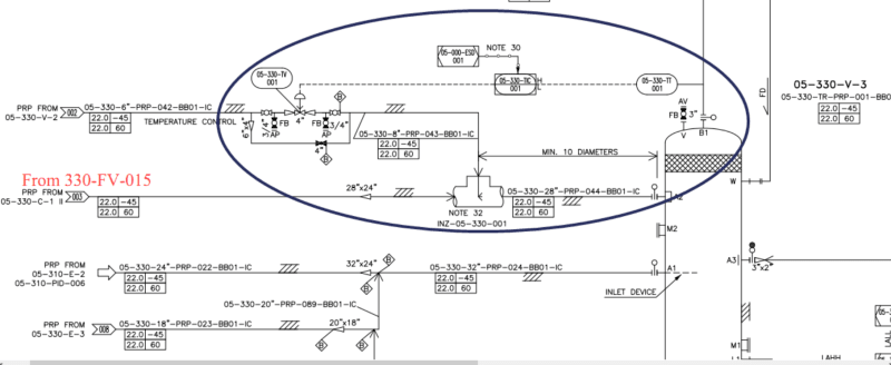
TV_fqehqp.png


Operational Parameters:
Operatioanl_Parameters_i0ijc5.png


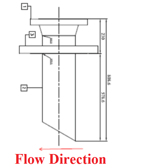
Current liquid nozzle injection:
Current_Spray_Nozzle_zbl1ik.png

 
Replies continue below

Recommended for you

33 ton/hr is a lot to inject into a 138 ton/hr line. The kinetics of drop breakup and vaporization do depend on droplet size, so I am in agreement with you - why no spray nozzle?

If your gas velocity is high enough, you could use a full cone nozzle and spray counter-current to the gas flow - ala a reverse jet scrubber design. You will get a little higher pressure drop, but is about the most intense mixing you can do (lowest chance of droplet carryover/accumulation. Barring that, if you inject perpendicular to flow, I would suggest a fan nozzle, not a full cone nozzle.

Edit: Bete Fog is also a good, reputable spray nozzle company that I have used in the past.
 
Hosein ....

IMHO, spray nozzle configuration and sizing is a field that is on the border between witchcraft and engineering.

I do not believe that you will find an authoritative answer on these fora ....

Go directly to the spray nozzle vendors and talk with their R&D department....

I have experience with spray nozzles in the paint and resin industry. I am convinced that you need engage and pay for the expertise of someone who has been doing this for a long time

These fine people are the best in the business ....

Spraying Systems Company
U.S. Corporate Office
200 West North Avenue
Glendale Heights, IL 60139-3408
Phone: +1 630.665.5000


MJCronin
Sr. Process Engineer
 
Think this is a more a process controls issue than a mixing issue. Running this on a simple TIC loop is prone to result in over injection as the TC is likely to over shoot (and also undershoot), resulting in liquid formation in this suction KOD. If the TIC setpoint is correctly set, it should result in slightly superheated gas to the suction of the compressor, with no liquid in the suction drum. See if you can reconfigure this TIC loop to stabilise the loop and also decrease response lag of the TT:
a) Use a thin walled thermowell for the TT.
b) Use a thermocouple type TT rather than RTD type
c) See if you can come up with a cascade loop rather than this simple TIC loop.

Also, it would have been better if this liquid injection assembly be relocated to the main feedline PRP - 024, rather than on the antisurge line PRP-044. On the ASV line, when ASV flow is small, liquid mixing into gas will be poor. While there is much more gas going through the main feedline all the time.

Using a spray nozzle would help with better mixing, but I dont know if Bete has nozzles going up to 6inch.
 
By looking at the the temperatures this nozzle type will be the cause of the brittle fracture on the main due temperature gradient with the injection. Of course it depends on the wall thickness and the additional pipe stresses at that location and the flow rate of the injected liquid propane.

Similar applications are used in the boilers by injecting water into the steam to tune up the final steam temperature, and most of the designer companies use liner in the mix area with the water injection into the liner. Water injection is always in the main steam direction, not with a cut as given by OP. Some others provide atomised water injection into the main steam line with/without liner.

So you need to talk to the designer of the injection area and get their assurance.


The temp is no problem with austenitic SS parts.
The real issue is what George pointed out, control balance.
Often this is done in stages, one nozzle or sparger (tube with holes) for 80% of the flow, and then a smaller spray system for the fine adjustments. But system response must be fast. This is an issue with both sensors and controller tuning.

= = = = = = = = = = = = = = = = = = = =
P.E. Metallurgy, consulting work welcomed
 
Dear georgeverghese and EdStainless.
Thanks for your kindly reply.
As a matter of fact, we don't have any trouble with Temp. controller adjustment. Because this simple control loop is actually a slow response controller, so we can control temperature reduction very well with no overshoot or undershoot. But as I told you, when we reduce temp. below -21 C, liquid PRP would be formed in KOD.

Dear georgeverghese.
I'm not agree with you about relocation of temp. control line. Because main feed PRP line temp. is about -32 C, and ASV line temp. is about 80 C.

Thanks three of you, saplanti, georgeverghese and EdStainless.
 
I disagree with georgeverghese in this case - all injected propane should vaporize at your conditions since your main process stream is kept at ~0.08 barg. Propane vapor pressure at -21 C is ~1.4 barg, and at -34 C is ~0.5 barg. If this were a just a controls issue, any overshoot of injected propane should still vaporize at these conditions, and you'd see a variation in process temperature, not liquid accumulation. The OP is not seeing variations like that.

The only reason that more propane would not vaporize at these conditions is that the initial vaporization cools the liquid enough that the actual vaporization rate is controlled via heat transfer. The vapor pressure of propane equals 0.08 barg at ~-41C, so it doesn't take very much vaporization to cool the bulk liquid propane from -32C to somewhere near saturation temp.

This is related to injected particle size and bulk fluid temperature. Smaller particles will require less residence time than larger particles for full vaporization. However, the more you inject, the cooler the bulk fluid temperature becomes and the slower the particles will evaporate (due to lower dT). At some point, the residence time for vaporization of the droplets becomes large enough that they impact the KO drum and re-combine on the drum surfaces. As they re-combine, surface area is drastically decreased and vaporization rate drops.

Jack - can you provide any data for injection ratio (injection rate/(NG rate+injection rate) verses outlet temperature ? If I am right about the limit being heat transfer, you should see a fairly steady decrease in temperature with increasing injection ratio. At some point you should see an inflection point in that curve where additional injected liquid starts experiencing severe diminishing returns as some of the liquid is not vaporized.


My $0.02 is that atomizing the injected fluid should increase heat transfer rate and allow lower bulk fluid temperatures without liquid accumulation.
 
Agreed, if the TT reads -21degC only at this low pressure, all liquid injected should have still vaporised, in theory. Liquid would form at this pressure, at equilibrium conditions, at approx < -34degC or so for pure C3. The fact that it hasnt reached equilibrium even at -21degC is a mass transfer rate issue.

You could line up a series of spray nozzles along this recycle line to enable a total of 33t/hr. The available dp of <0.4bar for the spray nozzle is a big constraint. A good 2-3bar dp would be better to get good atomization. Locating this multiple spray nozzle assembly further upstream will also buy time to enable vaporisation. Talk to Bete or other vendors to set this up.

Ideally, this suction drum should be fitted with a say 2m high packed bed (or wiremesh bed) where injected liquid would flow countercurrent to gas rising upward to get better vapor liquid contact . Drum dia would be suited to prevent liquid from backing up. You'd be most likely be looking at a new drum.

Why is the stage 1D recycle gas at 80degC? Presume there is no cooler on stage 1D? Another alternate would be to cool stage 1D recycle gas, first with an air or water cooler to say 45degC, then remove residual heat with a C3 chiller kettle HX which is floating on stage 1S pressure (with both air cooler and C3 kettle chiller upstream of ASV). Quantity of liquid C3 used for this scheme would be less than you are using now for obvious reasons. It is also obvious, that your EPC contractor for this plant used a cheaper scheme of direct injection to reduce CAPEX in comparison to this alternate cooling scheme with HX which has higher CAPEX but lower OPEX. As such, it is now obvious that there is limited use in trying to correct this design error by improving on liquid - gas contacting by direct injection.
 
Status
Not open for further replies.

Part and Inventory Search

Sponsor