Hello,
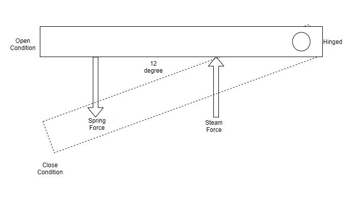
I am trying to design a emergency trip lever which is hinged at one end and closes the steam valve under the action of spring force.Valve shuts off by impacting on valve seat. Please Refer the figure. I want to calculate the spring stiffness for the motion of 12 degrees within 1 second. Length of lever= 525mm, width =38 mm. Spring force acting at 301 mm from hinge. Steam Force acting at 140 mm from hinge. Mass of lever considered acting at 245 mm from hinge. Mass of lever = 2.5 kg , Moment of inertia considered =0.23 kg-m^2
I have considered lever as rigid and from newtons law. I am getting differential equation as
y''+0.4ky=0.08k-477, where , k= Stiffness in N/m

My doubts
1. Considering even k= 17000 N/m, differential equation shows cycle time of 0.02 sec which is quite fast since inertia is less. How to asses the safety of the operation?
2. How to calculate energy dissipated when lever closes /impact force on valve seat. here it needed that valve should remain closed as soon as valve hits on valve seat.
3. Does the system need damper or by designing strong cross section, this system can be made practicable?
I am new in this field, Kindly help.
Thanks.
Regards,
Suraj
I am trying to design a emergency trip lever which is hinged at one end and closes the steam valve under the action of spring force.Valve shuts off by impacting on valve seat. Please Refer the figure. I want to calculate the spring stiffness for the motion of 12 degrees within 1 second. Length of lever= 525mm, width =38 mm. Spring force acting at 301 mm from hinge. Steam Force acting at 140 mm from hinge. Mass of lever considered acting at 245 mm from hinge. Mass of lever = 2.5 kg , Moment of inertia considered =0.23 kg-m^2
I have considered lever as rigid and from newtons law. I am getting differential equation as
y''+0.4ky=0.08k-477, where , k= Stiffness in N/m

My doubts
1. Considering even k= 17000 N/m, differential equation shows cycle time of 0.02 sec which is quite fast since inertia is less. How to asses the safety of the operation?
2. How to calculate energy dissipated when lever closes /impact force on valve seat. here it needed that valve should remain closed as soon as valve hits on valve seat.
3. Does the system need damper or by designing strong cross section, this system can be made practicable?
I am new in this field, Kindly help.
Thanks.
Regards,
Suraj
