CoolCat83
Mechanical
- Aug 29, 2022
- 5
I'm an engineer who started a new job assisting with project management and the like, and one of the things was the check the sprinkler design that was proposed for one of our buildings, not sign off, but just to get an understanding. It doesn't need sprinkler yet, but more levels may come, so owner/engineer wants to be ready.
I found this website where they go through a sample calculation and it seems straight forward enough:
Hydraulic Calculations
Basically start at farthest sprinkler, assume a flow or pressure per the minimums, then calculate the sprinkler flow/pressure via discharge formula, then work backwards using Hazel-Williams friction losses. Easy enough.
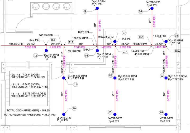
They did an example, and they ended up with this:

They started at 1, assuming 15 gpm/7psi, worked back to 2, solved for a new pressure/flow then junction 2A to get a pressure of 11.544 psi, and this is where I get lost. How can they assume that tiny branch to 3 will see the same pressure drop as the 10x longer branch to 1? They can't. Which means the pressure/flow is going to be considerably higher than 15gpm at 3, as the pressure will not drop from 11.544 psi to 7psi. More like 11 psi at best, resulting in a flow of something like 18.6gpm.
This in turn means that the flow rate from 3A to 2A will not be 45.6 gpm, but 49.2 gpm, which in turns means the friction will be higher, which in turn will result in lower pressure at junction 2A, which in turn lowers flow to sprinkler 3, which in turn decreases friction and it goes on back and forth until in more or less stabilizes numerically. This is possible to do in excel, just put in circular references and have it run until the values stabilize, and is most likely how various numerical CFD systems work to evaluate fire suppression flow.
The further problems in that the author just copies Branch 1-2 into 5-6 and 10-11. Essentially every sprinkler aside from 1 is going to see pressures and flow higher than 7psi/15gpm (unless you incorporate specific throttling valves etc), could all these increased flows (and associated pressure drops) not leave you with a system somewhat under powered?
Am I missing something? Or just vastly over thinking it. Additionally I was told that really only the last 3/5 heads need to be evaluated, as all heads won't be likely to go off at the same time, so is that just enough of a safety factor there to account for the potential lack of pressure or flow?
I found this website where they go through a sample calculation and it seems straight forward enough:
Hydraulic Calculations
Basically start at farthest sprinkler, assume a flow or pressure per the minimums, then calculate the sprinkler flow/pressure via discharge formula, then work backwards using Hazel-Williams friction losses. Easy enough.
They did an example, and they ended up with this:

They started at 1, assuming 15 gpm/7psi, worked back to 2, solved for a new pressure/flow then junction 2A to get a pressure of 11.544 psi, and this is where I get lost. How can they assume that tiny branch to 3 will see the same pressure drop as the 10x longer branch to 1? They can't. Which means the pressure/flow is going to be considerably higher than 15gpm at 3, as the pressure will not drop from 11.544 psi to 7psi. More like 11 psi at best, resulting in a flow of something like 18.6gpm.
This in turn means that the flow rate from 3A to 2A will not be 45.6 gpm, but 49.2 gpm, which in turns means the friction will be higher, which in turn will result in lower pressure at junction 2A, which in turn lowers flow to sprinkler 3, which in turn decreases friction and it goes on back and forth until in more or less stabilizes numerically. This is possible to do in excel, just put in circular references and have it run until the values stabilize, and is most likely how various numerical CFD systems work to evaluate fire suppression flow.
The further problems in that the author just copies Branch 1-2 into 5-6 and 10-11. Essentially every sprinkler aside from 1 is going to see pressures and flow higher than 7psi/15gpm (unless you incorporate specific throttling valves etc), could all these increased flows (and associated pressure drops) not leave you with a system somewhat under powered?
Am I missing something? Or just vastly over thinking it. Additionally I was told that really only the last 3/5 heads need to be evaluated, as all heads won't be likely to go off at the same time, so is that just enough of a safety factor there to account for the potential lack of pressure or flow?
