Continue to Site

Eng-Tips is the largest engineering community on the Internet

Intelligent Work Forums for Engineering Professionals

  • Congratulations GregLocock on being selected by the Eng-Tips community for having the most helpful posts in the forums last week. Way to Go!

Square concrete tank - too tall to work? 2

Status
Not open for further replies.

Screwtape

Civil/Environmental
Jul 27, 2005
19
Currently working on the design of a rectangular shaped concrete tank consisting of two 60' square tanks that share a common interior wall. It's retaining 21 feet of water, the bottom of the tank about 10 below grade, and the top is open (see sketch).

I've done several concrete tanks but none as tall as this one. Ran through a preliminary design and I think I can get the vertical and horizontal moments to check using a tapered wall section. But overturning is an issue even with a thickened footing (30" thick) under the walls. Soil pressures are not even close to allowable, as the geotech has given me 2500 PSF to work with.

Any suggestions or tips for tall walls such as this? I'd rather avoid piles if possible. Will probably reach out to the client to see if circular tanks could be used but not sure there is enough room on the site.
 
 https://files.engineering.com/getfile.aspx?folder=e9690470-52c3-4c5e-9999-222f6daea33d&file=Tall_Tank_Sketch.pdf
Replies continue below

Recommended for you

I'm not following you on overturning. How could you overturn the whole box?

How are you calculating your bearing pressures? Are you doing a finite element analysis or some other methodology?

I would think your worst bearing pressure would be a tank empty situation. The lateral earth pressure would drive the 'toes' of your wall into the soil. But, the mat foundation should smooth out and reduce this pressure if stiff enough.

When the tank is full, you would pick up 21ft*62.4=1310psf of vertical pressure, but that same water pressure would negate or significantly reduce the lateral earth load driving the toe into the soil.
 
Put your tank on a mat slab.

I'm with Joel....this isn't going to overturn if the slab/footing is designed properly. I disagree that the active soil pressure will govern wall design. You likely will leak test this empty (or could they excavate around the tank when it's full for some unknown reason...) so you won't have passive earth pressure to counteract the hydrostatic force.

Have you considered buoyant forces? That could govern design of your tank floor.
 
I treated the wall like a cantilevered retaining wall. Conservative, I know, but I wanted to see what kind of resistance against OT it would have with service level loads. The slab/mat beyond the perimeter footing is very stiff so the wall acting like a cantilever RW is unrealistic.
 
A circular tank would be the way to go if there is room on site. Even if there isn't, a pair of circular tanks with 60' diameter and 27' water level may be worth exploring. Carrying water pressure by ring tension is going to require much less reinforcement and the soil pressure will be less than 2500 psf.

What is the water used for? Fire fighting?


BA
 
I've done a bunch of tanks exactly the same as that. This is not that tall of a wall.

[li]The tapered walls look good, but the griping from the contractor will over whelm any savings. No harm in doing it, but expect some pushback.[/li]
[li]I'm not sure why you're having problems with overturning. You will get a small higher stress at the edge, but it should go down quickly. Your average stress should be your dead load plus 1323 psf. You can analyze the slab as a footing with a moment on it and take as much of the width of the tank as you need to balance the moment on the wall. Don't forget, you have 21 feet of water over the slab. Your moment at the edge is 84 ft. kip unfactored. You need about 11'-6" of slab to balance that. And that's just the liquid on it, your dead load helps. But you're going to have to thicken the slab for that distance. If the bearing pressure still higher than 2500 psf, talk to your Geotech. If he or she understands it's a small area, you might get a local higher stress. [/li]
[li]I don't think a 30 inch slab is unreasonable. It's just going to have to be longer. By the way, tapering to a thinner slab is another case of false economy, but someone is going to comment on it if you don't do it.[/li]
Don't worry too much about the amount of concrete. These structures take a lot of it.
 
Slightly different subject here, but the cantilever assumption is conservative for vertical moments in your wall, but it is not conservative for horizontal moments.

If you are not already using them, then I would suggest using the DOI tables for flat plates. For the tank empty situation, they have a table for a triangular load 2/3 of the way up a flat plate. If you assume your dirt load is 2/3, then that table would be applicable.

For tank full scenario, then you just assume a triangular load all the way to the top.
 
This is a new tank in a wastewater facility.

Thanks to all for the suggestions and questions. I'm still early in the design so I still have to resolve some things.

On a different note, does anyone have the errata for the PCA publication? I have the book as a PDF but don't have the extra.
 
I've heard about the BOR document but this is the first time I've seen or used it.

The table format is throwing me off. Could someone look at page 10 and verify something for me?

a= 60/2 = 30'
b= 21'
a/b=1.43 (use 3/2 section in table)

What are the moment coefficients at the center-bottom of a plate?

[EDIT] Nevermind. Got the vertical, horizontal, and shear coefficients worked out and they track with my previous numbers (using the PCA tables). Was looking at the table wrong.
 
I have used the PCA document in the past, but as Jed mentioned....it has errors in it.

The Dept of Interior's (DOI) document that JedClampett cites is easier to use once you get the hang of the tables.

For your parameters, I get the following with a/b=3/2

Case 1 & Loading 4
Max Rx = .3127 (this is shear at the top of the wall (y/b = 1 and x/a=0) where the sidewalls intersect)
Max Ry = .5047 (this is shear at the base of the wall out in the middle (y/b=0 and x/a =1)
abs value Max horizontal moment Mx = .0857 at top of wall and x/a=0
abs value Max vertical moment My = .1262 at base of wall and x/a=1

Capture_v749do.jpg
 
For the bottom plate, the moment coefficients shall be read off from the interception of y/b = 0, x/a = 0 and a/b = 3/2.
 
That's the coefficients I got as well. Thanks for checking.
 
Just as a word of advice, you need to get ACI 350 and use its crack control and load factor criteria. The load factors in ACI 318 are wrong for fluid loads. They've been wrong for 50 years and I don't see them ever changing.
[ul]
[li]For shear, use 1.7, unless your using reinforcing to resist shear.[/li]
[li]For moments or shear stirrups, use 1.7 x 1.3=2.21[/li]
[li]Don't take the shear at "d" above the slab. Take it right at the interface.[/li]
[/ul]
 
Thanks Jed.

I'm already using the higher load factors dictated by ACI 350. 1.7 for fluids from 318 plus the sanitary coefficient of 1.3 where applicable.
 
Is there a possibility of significant unbalanced pressure on the wall separating the two tanks?

BA
 
BA,

Yes, it is the maintenance stage that needs to be checked and designed, it usually governs.
 
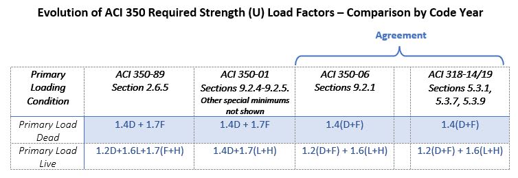
I thought the fluid 1.7 load factor was in ACI 350-01, but then got moved to the appendix in ACI 350-06 as an alternate procedure. Now the load factors between ACI 350 and ACI 318 are treated the same. You just have to add in the sanitary coefficient.

For shear and flexure the sanitary coefficient will vary based upon the calculated 'gamma' variable.

I made this table because I got so confused over the subject a year ago.

Capture_uyitsj.jpg
 
Your internal wall looks mighty thin and will take a bending load when one take is full and the other is empty.
 
The old school always check the maintenance/unbalanced conditions. I wonder it is still the norm these days.
 
Status
Not open for further replies.

Part and Inventory Search

Sponsor