Continue to Site

Eng-Tips is the largest engineering community on the Internet

Intelligent Work Forums for Engineering Professionals

  • Congratulations cowski on being selected by the Eng-Tips community for having the most helpful posts in the forums last week. Way to Go!

SSR Relay stuck in active position 4

Status
Not open for further replies.

jozaeta

Bioengineer
Nov 19, 2005
13
Before I begin, I am completely out of my element in this project, so my apologies if I don't use correct terminology.

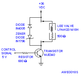
I am trying to control a microliter dispensing valve using a relay control circuit. This circuit needs to be fast, as I need the droplet sizes to be very small. My digital IO controller outputs a 5V TTL signal, which used to drive a 5V reed relay (with a 51V zener diode parallel to the relay for protection). The common pin of the relay is connected to a +13.8VDC 3A power supply, and the normally open pin is connected to the positive end of the dispensing valve. The negative end of the valve connects to the negative end of the power supply. The valve is supposed to be driven by 12V, with a threshold current of 0.209 mA.

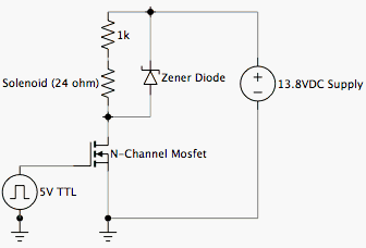
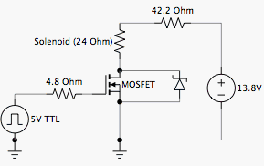
With the reed relay, I was able to get a decent dot size of around 5 mm, but this valve is supposed to be able to make dot sizes smaller than that. Therefore, I switched over to a solid state relay (input is 5V; output is 120VAC 1.6A) in an attempt to possibly make the circuit respond faster.

However, following the same wiring scheme as with the reed relay, my results were not what I expected. The relay closes with no problem. However, once the relay is in the closed position, it appears to be stuck in the closed position even when the 5V input is cut off. If I remove the valve and just put a voltmeter to see what's going on, the circuit acts as expected. What's going on?

Did I choose the wrong kind of SSR relay, or is there something wrong with my wiring or choice of power source?
 
Replies continue below

Recommended for you

AC type solid state relays are either made with triacs or back to back scr. In either event, when they are triggered they stay on till till the current is removed. In normal operation this is accomplished by the 60 cycles of the AC power. I've built high speed solenoid drivers. Did a glue application where I had to make dots, 2ms on 2 ms off. I used a fuel injector driver IC from National. If you want speed, you drive the coil with a lot of voltage and then current limit it so it will also turn off fast. Use the chip and it will be much faster than those off the shelf blocks.
 
Thank you for the replay OperaHouse. I will look into fuel injector drivers.

But given my current setup, is there anything I can do to limit the current then once the output signal is shut off? Or should I look for DC type solid state relays instead?
 
You didn't state how fast you are trying to cycle the relay. However, you indicate the output of your SSR is controlling the solenoid with 120VAC. You need to be aware that many SSR relays for AC circuits are designed to switch at the zero AC crossing (to minimize transients and EMI). Many SSR relays will not retrun to the off state until near zero current is flowing through the relay.

If you are working with 60 cycle AC, the quickest you may be able to switch a SSR is 1/120 sec. If 50 cycle then 1/100 sec.

Since you've already tried swithing the solenoid with DC (using a reed relay), instead I suggest you use your DC solenoid and switch it on and off with a MOSFET or transistor. You can find logic level input MOSFETS which will work directly from your 5V TTL signal.

Switching DC on/off at the ground side is simple with a N-channel MOSFET or NPN transistor. With a N-channel MOSFET drain or NPN transistor collector, you connect one end of your solenoid to your positive DC supply, and the other end to the MOSFET source or transistor emitter which switches to ground. Control a transistor with a resistor in series with the base (about 1K ohms). For a MOSFET, the TTL control signal goes to the gate. A resistor in series with the gate is usually not required with a MOSFET but you can have a resistor - in otherwords a N-MOSFET or NPN transistor are interchanable in such a switch circuit even though the name of the pins are different.

If you must switch on the high (positive) side then you can use a P-channel mosfet or PNP transistor. Logic level translation to drive this arrangement takes a little more consideration but you should be able to find simple circuits with a web search. P-MOSFETS or PNP transistors are not as fast in switching, but the difference for such a circuit is in the microseconds.

A diode should be place across the solenoid coil to provide a path for the flyback from the coil as the device switches to the off state. Cathode of the diode to the positive connected solenoid side. This is the same principal as the 51V zener you used previously.
 
Thank you for the informative response Comcokid. According to the spec sheet for the valve, the maximum frequency i can use is 600 Hz at 12V.

I just did some research on mosfets, and it does appear that I can use them to switch my circuit. I'm a bit confused on N-type and P-type mosfets. Since my driver outputs 5V to activate the valve, wouldn't I actually want an N-type mosfet? And are most mosfet gates tripped with voltages ranging 2-7 volts? I tried looking on an electronic component site for a mosfet I can use, and they don't list the gate voltage, only voltage and current ratings.

If that is correct, then would this picture be the way I should wire my circuit?
circuit.gif
 
jozaeta; Your circuit looks good. However you should put the diode across just the solenoid. Use a regular diode not a zener.

Yes, just use an N-Type mosfet as you have it.

You should use a mosfet that is called a "logic" mosfet. They are specifically designed to be turned more fully on by 5V then typical fets that need about 7 to 10V.

Go to International Rectifier. They are the pros in that field and they have a good site.

Pick one with about 55V or more.

Go to the BOTTOM where there is a RDS of 4.5V. Pick any of these.

This might work, you never said what the current of the solenoid was.
 
Thanks for the help itsmoked. I'll be sure to wire the diode across just the solenoid. Probably a dumb question, but why would using a zener diode be inappropriate for this circuit? I'm afraid I'm not too keen on the differences between various types of diodes, nor what a regular diode is called (switching diode?).

The threshold current for my valve to be about .209 A. The continuous voltage (5VDC) and the coil resistance 24 Ohms were used to come up with that number. Here is a PDF of the drawing for the valve:
 
A zener is a special diode meant to avalanche (or is it breakdown?) at a specific voltage. The "zener voltage".

The coil when un-energized will cause a large inductive voltage kick that will be a polarity that is opposite of the driven polarity. You want none of this to get to the fet. But due to the Dirac function (Straight up) if you tried to just block it, the voltage would sky rocket (hundreds of volts) probably breaking something.

So the solution is to put a standard diode in parallel with the coil and reversed to the normal flow direction. It will then in effect short the previously mentioned voltage spike thru the inductor/coil itself. The resistance that is inherent in the copper winding of the coil will dissipate this shorting current without damage.

You can probably use a regular "rectifier" type diode. But I would use a faster one. Something like:

The fet I mentioned b4, is probably over kill but if you are just making one or two units it will take some abuse and be easy to handle. So I'd still use it.
 
DON'T PUT THE DIODE ACROSS THE SOLENOID! At least not if you want any speed on turn off. As a rule, use as high a value zener or MOV as the driver can tolerate. A little curious about the .209ma you stated and the 12ma circuit you show. 12ma isn't much of a valve. People here often put the decimal in the wrong place. I checked into the LM1949 (you can get free samples) I mentioned and it is only available in a mini dip package. That could be a chalange to work with. I don't see any reason why you can't use a simple NPN transistor at these currents driven by a 470-1K resistor to the transistor base from your 5V logic. The resistor in series with the coil to limit current is probably the simplest way to limit current with the higher voltage for faster turn on. What problems were you having with the reed relay?
 
Ok. I have to admit that I'm a bit confused now with conflicting information. So for the fastest performance while maintaining safety, I should put the diode in series with the solenoid? Should I use a regular diode or a zener diode now?

Are you saying the circuit I drew will not provide enough current to the valve? Because I just did some calculations and, depending if I did them right, it does seem that I'd only be providing a 13mA current, when the valve needs 209 mA (why am I not getting .209mA as you stated? Isn't V=5V, R=24ohm, therefore i=V/R in amps?). If that is the case, would I just have to use a smaller resistor instead of 1k? But don't I need that 1k resistor?

Again, thank you for the help in this very confusing matter.
 
Well "Normally" you put the diode, a "regular diode", just as I've stated across ANY DC coil as we've discussed. OperaH is talking about trying to dissipate that stored energy faster..hence causing the magnetic field to collapse faster. Making the valve close faster. I haven't personally messed with speeding up solenoids. If he has, he may have knowledge I don't about the subject.

As for the current. He's probably confused by my accidental inclusion of a decimal point. .209 = 209mA I switched in the middle of the stream because typically currents under an Amp, EE's switch to mA. [colorface]

I was confused by your 209mA.

I get that with V/R=I 5/24 = 208mA

Your circuit I'm looking at above is 13.8V.

13.8/24 = 0.575mA

or 13.8/(24+1k) = 13.5mA

If you need 208mA but want to use 13.8V then you need a different resistor.

V = I X R; V/I = R; 13.8/208mA = 66.5Ohms

66.5 Ohms - 24 Ohms = 42.5 Ohms

42.5 is what you need.

Don't forget that: Power = I x I x R.
Power = 208mA x 208mA x 42.5
Power = 1.8 Watts.

You should stay below about 1/2 the resistors rating for reliability... You need a 3 or 4 watt resistor. (Big)
 
That sounds better. You would have to drive the transistor base with a 400-500 ohm resistor to get enough drive. A little better circuit would be to put a 3.3 ohm resistor from the emitter to the - supply. An additional NPN transistor would also be added. Emitter to - supply, base to top of 3.3 ohm resistor, collector to the base of the driver transistor. This would make a constant current source. As the current rose to .7 volts, this additional transistor would begin to sink drive current away from the output transistor. A constant current would be maintained and no additional resistor would be needed in series with the solenoid. Adding a capacitor across the 3.3 ohm resistor will also give you a short duration higher on current for faster operation. Potential problems are that your 5V pulse source may not have sufficient drive and that the transistor will produce a lot of heat. If that fails there is no protection for the solenoid. Transistor should be rated for at least 100V and zener should be about 60V. I used to drive 6V solenoids with a 50V supply. At 200ma you are likely just short of the drive current needed and will have to use a darlington transistor, even more heat!
 
I'll put that better circuit into consideration. But backtracking to the basic circuit I drew, with the zener now in series with the solenoid (with the anode connected to the positive end of the solenoid and cathode connected to the other resistor), I would need a small resistor (like the 42.5 Ohms that itsmoked said). Is it safe to lower the resistance from 1k to 42.5?
 
Well, the circuit you posted with a N-chan FET is pretty
scary. Not that FET's are inappropriate, but they DO need
to be handled a bit differently than BJT's. If you do use
an FET, make sure you add a gate resistor to one of the
rails, or add some sort of gate driver. There are numerous
examples of such at: Root around. There are plenty more examples.

I won't post the simpler relay drivers (probably gazillions
available to a search engine, but here are some that solved
a particular need (all level-shifters with TTL inputs:
and one with current control:
All are probably overkill for driving a small relay, but
should give you an idea of the components and some general
values. A single 2N2222, 2N3904 or similar small-signal
general-purpose transistor would probably suffice for your
purpose.
<als>
 
The zener should be across the FET or transistor. Just move it down in the drawing. As shown, the zeneracts mostly like any other diode. Some FETs will have this zener internally.
 
Ok. I've probably exhausted my welcome asking such elementary questions, but I redrew the circuit based off of all your posts. Does this circuit look any better, or is it just as bad?

circuit2.gif
 
You want the diode across the coil of the solenoid, unless you want to discharge all of the energy through your circuit. The whole point of the diode is to disapate the energy that is released from the coil, inductor, when one side drops out. If you don't disapate that energy something, the voltage will either fly high or low (depending on which side of the relays drops out), and cause some other component failure due to overvoltage stress. Therefore, you want to keep the energy disapation device, the diode, across the terminals of the relay. If you move the energy disapation device away from the coil, another, unsuspecting circuit may breakdown before your diode gets a chance.

As far as diode vrs zener, it doesn't really sound like switching speed is all that critial. Therefore, it would be much cheaper to use a sloppy old 1V4001 type diode to disapate the energy from the coil. Remember, size your diode approriately based on the amount of current the is flowing through the coil when energized (this will be the maximum amount of current that can be instaneously supplied by the inductior when the voltage drops out).
 
That has no evident faults. :)

The back emf caused by interrupting current thru an inductor, that would seriously abuse the fet, is now going to be handled by the zener. The zener voltage should be about half the rating of the fet for its safety. According to Ohouse I guess that stored energy can be more quickly consumed by the zener and the power supply than by recirculating it thru only the coil.


Something we've all left out is that as your circuit sits you could turn on the solenoid and leave it on indefinitely as long as you have that resistor wattage correct.

However if you have a duty cycle over a period of a second you can mess with the resistor's resistance value and power rating.

For instance if you are allowed 208mA continuously then if you are never ON more than say, half the time, 50% duty cycle, then you could probably decrease the resistor value for quicker opening. Or conversely, use a lower power resistor because the average power thru it will be less.
 
Would you state for the record just what you would like the on time and off time to be. I got the idea that you would be making continuous dots. How long would you run this for? Do you have a source of higher voltage other than the 13.8V? This could be insufficient for the speeds you want to run at.
 
I am trying to get response times down to 2-5 ms. I just discovered a high-speed circuit example from the manufacturer of the valve. It is very similar to the diagram I drew, except the diode is in the location like melone and itsmoked said. Their diagram shows two diodes, however. It looks like I can adapt my circuit to this setup, yes? In my case, I would be using a logic-level n-type mosfet, and the 13.8V source (but I may up that voltage if the circuit still reacts too slow). Could I use a small resistor for the gate though?

42c.gif
 
Status
Not open for further replies.

Part and Inventory Search

Sponsor