Continue to Site

Eng-Tips is the largest engineering community on the Internet

Intelligent Work Forums for Engineering Professionals

  • Congratulations KootK on being selected by the Eng-Tips community for having the most helpful posts in the forums last week. Way to Go!

STAAD Compression Springs Issue 1

Status
Not open for further replies.

swearingen

Civil/Environmental
Feb 15, 2006
663
I'm quite sure I'm pressing the wrong button on this thing, but I can't seem to find the button...
My situation:

- Trussed industrial tower with various types and sizes of spread footings underneath.
- Lateral wind and seismic applied.
- Structure consists of steel members.
- Footings consist of concrete solids.
- Springs using a subgrade modulus of 100 pci for the stiffness (100pci x 144in^/sqft x 12in/ft / 1000lb/k = 172.8 k/ft spring stiffness per node associated with 1 square foot).
- Compression only spring specification added to the nodes at bottom.
- Lateral restraint at top of pedestals applied (grade beams between columns).

I'm getting a deflected shape that shows the entire tower rising off the ground by hundreds of inches. Things I've checked:

- Selfweight is vertical axis Y and -1.
- All loads have correct signs; gravity and equipment loads are all -Y.

It's obviously not right (as you can see from the picture). Where else can I look for errors?

Thanks in advance,

Frustrated Engineer
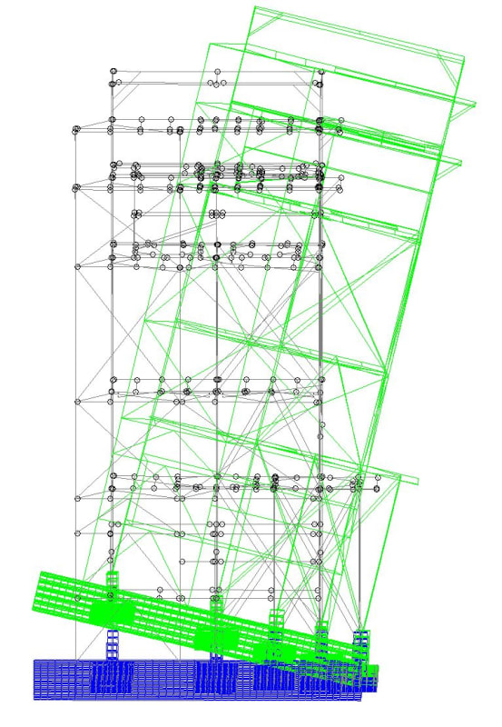
Tower_rakiy5.jpg


-5^2 = -25 ;-)

 
Replies continue below

Recommended for you

I assume that Sye123 was referring to structural mechanics and the conventional FEM formulation, in which 3D deformation is represented by displacement components (w, v, u), and no rotation. This is the formulation that I have seen in university and in textbooks, and it is the only formulation that makes sense, if you think about it a bit further.

Absolutely. But rotational degrees of freedom for solids are not unheard of. DYNA (for example) has elements with this capability (see the attached pdf).

I've heard that some of the higher order elements (i.e. isoparametric) are very flexible as well. I.e. elements like the 27 noded brick (with or without rotational degrees of freedom). So that's one of my reasons for asking Sye: is STAAD doing something we aren't aware of? (I.e. a internal isoparametric formulation or whatever.)

In any case, STAAD must be doing something about this internally because of the changes I noted in a previous post. (I.e. no error warning with a fixed node on a solid & more flexibility.)

 
 https://files.engineering.com/getfile.aspx?folder=331eed38-07c8-4ba5-b123-953d9a243358&file=K-03-Isogeometric-and-FE-Technology-Schmied-DYNAmore_(4).pdf
@JoshPlumSE
Perhaps the FEM book by MacNeal you are refering to is Finite Elements: Their design and performance. In the chapter about shell elements he describes that the early elements were derived from solid elements. He describes the challenges when creating the drilling dof and even if I don't see it stated it seems that in Nastran it was skipped to beging with. As a Nastran user I know that today Nastran has quad/tria elements with and without drilling dofs. The recommended is with I believe.

I had i quick look at the pdf from WARose. The approach in LS-Dyna seems, based on a figure, to be similar to something I read in a paper recently. In the paper they described how they started with a 2nd order brick, without rotational dofs, and created a 1st order brick, with rotational dofs. They reformulated the translational stiffness in the midside nodes to rotational stiffness in the corner nodes.

Personally I think I prefer the possibility for higher order elements rather then rotational dofs. I have not used STAAD for many years but I have colleagues that use it. But if the only purpose rotational dofs in a solid is to be able to better connect to a shell. THere are methods for that so I can't quite see the need for rotational dofs.
 
ThomasH said:
Finite Elements: Their design and performance

Yes, that is the book! I don't have access to it anymore because it was owned by one of my RISA colleagues. And, he probably bought it 30+ years ago considering when he was getting his master's degree.

And, thank you for some of the updates about these types of elements. That genuinely helps my understanding.
 
JoshPlumSE said:
Yes, that is the book! I don't have access to it anymore because it was owned by one of my RISA colleagues. And, he probably bought it 30+ years ago considering when he was getting his master's degree.

And, thank you for some of the updates about these types of elements. That genuinely helps my understanding.

It is nice to be able to help. You also made me curious and since I have the book it was easy to check. The book is nearly 30 years old since it was published in 1993.

Thomas

 
@canwesteng and centondollar: it appeared at first that it was standing on its toe, however, as I stated in the OP, the entire tower has positive Y deflections - every node - i.e., no spring has any compression whatsoever.

STAAD tech support (which has been very hit or miss in my experience over the years) did note that a CHANGE command was needed, and our seismic ACC parameter was far too high. This has solved the problem.

I still have an issue with case C, above. I just don't understand how any program could come up with all positive Y deflections with a net negative Y set of loads. Doesn't pass basic statics. STAAD even tells you it added some weak springs to tie the helium balloon down from flying away...

Thank you for all of the posts - some very interesting discussion that has increased my knowledge of how to handle solids and some things to look for. What a great site.

Keep up the good work, folks!


-5^2 = -25 ;-)

 
I just don't understand how any program could come up with all positive Y deflections with a net negative Y set of loads. Doesn't pass basic statics. STAAD even tells you it added some weak springs to tie the helium balloon down from flying away.

That's a sign of a modelling error so the results are questionable. Sometimes those weak springs paper over unimportant errors but other times the results are just arbitrary numbers because of the error - failure to find real solution. Some other programs would just report unstable structure and give no results. That's how seriously the weak spring warning should be treated.
 
I have not used STAAD for a couple of decades but if I remember correct it can't handle mechanisms. That's where the weak springs come as a solution.

If my memory isn't correct or STAAD has improved then I suggest running an analysis for natural frequecies. If there is something strange going on, finding rigid body modes can be an efficient way to find the "missing" constraints. Unconstraind parts will be "flying" around.

If it was my problem to solve I would start with Self weight only and try to figure out why, if any, springs are added. The springs could be a symtom for a global och local instability.
Keep it simple to start with.

Thomas

 
Status
Not open for further replies.

Part and Inventory Search

Sponsor