Continue to Site

Eng-Tips is the largest engineering community on the Internet

Intelligent Work Forums for Engineering Professionals

  • Congratulations KootK on being selected by the Eng-Tips community for having the most helpful posts in the forums last week. Way to Go!

STAAD PRO UNBRACED LENGTH

Status
Not open for further replies.

sedesigner06

Structural
Jan 10, 2014
58
I am using staad pro to evaluate a moment frame system. I am using the steel code check and I am getting an overstressed ratio on my frame beams that I know is not correct. Since the beam is see a negative bending moment it is taking the beams capacity as fully unbraced.

Is there a way in staad to have the program consider the bending inflection point to be braced? Or should I just look at the bending diagram and manually but in the UNB value.

Thanks in advance for any help.
 
Replies continue below

Recommended for you

The inflection point is never a braced point. Considering it such is incorrect. In staad you can (and should) be specifying the unbraced length for each member if it's braced at more or less than the node to node distance.

Professional and Structural Engineer (ME, NH)
American Concrete Industries
 
TME, I agree that in new design the inflection point should not be considered as bracing location. But if he's analyzing an existing system that was designed that way when it was acceptable, what then?
 
The laws of physics don't give preferential treatment to existing structures. I vote for adding / justifying some bottom flange bracing if your name's going on it.

I like to debate structural engineering theory -- a lot. If I challenge you on something, know that I'm doing so because I respect your opinion enough to either change it or adopt it.
 
I wonder if there have been any failures attributed to an under-designed beam designed using this old method.

I'm not arguing, more for curiousity. But my bet is no, and that is most likely due to not seeing the design loading.
 
My thoughts:
1) Back in the day when inflection point may have been considered a point of bracing, the Cb value was almost always taken as 1.0. So, there was some conservatism there. If you calculate a larger value of Cb you might still get the same beam to work with a longer unbraced length.

2) It may or may not be reasonable to consider the unbraced length to be the full length of the member. Maybe you've got a full depth shear tab or something else that will adequately restrain that beam for torsion or that bottom flange for lateral translation. That may be used to justify a lower unbraced length.
 
jayrod: I've never heard of a failure being attributed specifically to an assumed inflection point braced point. That said, I would suspect any such failures would just be reported as an undersized or under-braced beam and not attributed to the specific design error that led to the failure. A brief google search turned up nothing either. That said, it's fairly clear by research that this is not appropriate and in addition I've read it was never actually specified to be appropriate under AISC (not sure what AASHTO historically did).

I believe Josh has it correct, while the inflection points may have been taken as braced points the Cb factor was likely not considered and thus it likely washed out to approximately equivalent. I also suspect that the typical continuous or moment frame beams have sufficient unintended bracing from beams or decks attached to the member to add some lateral restraint such that if they are under-designed it's not a huge cause for concern in historic structures.

Regarding a re-design or update of an older structure, I fully agree with KootK's assessment.

Professional and Structural Engineer (ME, NH)
American Concrete Industries
 
I've certainly never heard of a failure. No doubt, the usual culprits factor in:

a) less load than expected and;
b) greater incidental, torsional restraint than expected (JP's point).

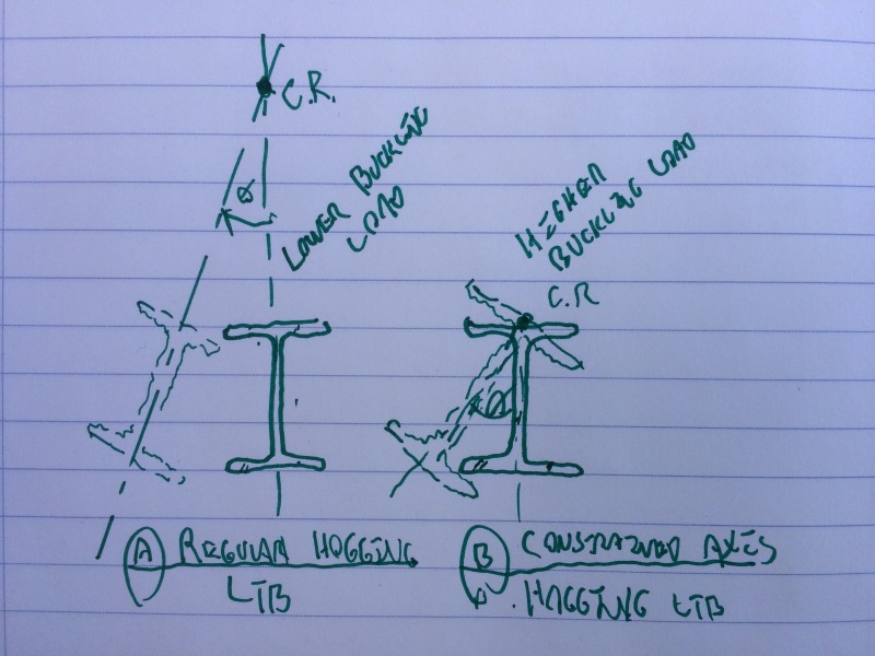
There is also something more demonstable however. That's the difference between regular, code LTB and constrained axis LTB. Constrained axis LTB numbers can be significantly better. If you have rotational bracing at the columns and any splices, and you run a constrained axis LTB check, it should be pretty rare that your capacity would come out less than the values calculated assuming IP as LTB braces.

The main problem with the constrained axis check is that it's not usually built into software and hand calcing it is a fee killer. Josh should really take care of that for us.

image_kgpcf6.jpg


I like to debate structural engineering theory -- a lot. If I challenge you on something, know that I'm doing so because I respect your opinion enough to either change it or adopt it.
 
Thanks for the insight, I will likely add an in-framing beam or a kicker to a parallel beam to brace the bottom flange until I see no negative bending moment in the beam. I believe that should do the trick to brace the bottom flange.

Thanks
 
Keep in mind the bracing strength and stability requirements in the AISC specification, often overlooked. A long, flexible brace connecting your flange to a springy beam does little to nothing.

Not sure what you mean about "until I see no negative bending moment in the beam". How is your bracing influencing your moment diagram?

Professional and Structural Engineer (ME, NH)
American Concrete Industries
 
Status
Not open for further replies.

Part and Inventory Search

Sponsor