Hello all,
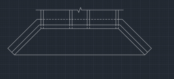
I am relatively new engineer still learning the most practical and efficient ways of analyzing certain problems. I have been asked to do an initial check of the stability of a proposed design for storm water headwall with wingwalls. I was told to evaluate the headwall and wingwalls as one monolithic structure vs evaluating them independently as separate retaining walls. The wingwalls are at 45 degrees and taper in height to match the proposed backfill grading. They share a slab between the wingwalls as shown in the plan sketch below. I have experience analyzing cantilever retaining walls as a unit strip but have not done a monolithic structure such as this with both the headwall and wingwalls combined.
I have a few questions in regards to how to y'all would approach this:
1. I assume the critical forces to check are driving forces (sliding and overturning) in the longitudinal direction (in direction of pipe culvert
alignment)?
2. Is it safe to assume the forces in the transverse direction will balance out since the wing walls are symmetrical?
3. Is there a simple way to compute the thrust on the wing walls in the longitudinal direction if the backfill height varies or should i check at
increments along the length and use the tributary area between the strips for the check (multiplying the resultant by sin 45)?
4. Is the configuration of the apron slab between wingwalls ok to terminate at the end of the wingwall length?
After the geometry is checked and modified to meet stability criteria, the strength will be evaluated.
Really appreciate everyone's insight and recommendations.

