Continue to Site

Eng-Tips is the largest engineering community on the Internet

Intelligent Work Forums for Engineering Professionals

  • Congratulations KootK on being selected by the Eng-Tips community for having the most helpful posts in the forums last week. Way to Go!

Stability of Footing with 2 columns

nrjdjjs

Structural
Apr 1, 2014
19
Refer to the attached image. Column 107 has no load and 1035 has a 200 kN load. There are no external applied shears or moments on either of the columns. The footing is 0.7 m thick and its top is at grade. What is the correct way to calculate overturning and resisting moments in this footing?
 

Attachments

  • 1734990568924.png
    1734990568924.png
    24.5 KB · Views: 30
Replies continue below

Recommended for you

First, I tend to assume that the footing is rigid. Which means I convert the loads / moments to an equivalent load and moment at the centroid of the footing. At that point, I use the same basic calculations that we use to determine the soil bearing and Overturning / Resisting factors that we use for a single spread footing.
 
200 Kip load on column 1035 is a downward acting compressive load.
JoshPlumSE - Thank you for your response.
So the overturning moment would be 200*2.25 = 450 kN m
Resisting Moment from the would be (200)*0.5*6.5 = 650 kN m if footing weight is ignored?
 
Refer to the attached image. Column 107 has no load and 1035 has a 200 kN load. There are no external applied shears or moments on either of the columns. The footing is 0.7 m thick and its top is at grade. What is the correct way to calculate overturning and resisting moments in this footing?

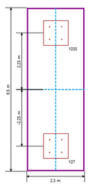
The size of the ftg 2.3 X 6.5 m and if the column 107 has no load , you do not need combined footing . If the attached picture is scaled , the column size should be around 1000X 1000 mm , and this column size is pretty sturdy for 200 kN load and meaningless for Column 107 which has no load.
I will suggest you ,
-provide spread ftg 2.3X2.3 m for column 1035
- provide spread ftg 1.5X1.5 m for column 107 and reduce the size around 400X400 mm ,

In your case , since the columns have not moment and shear , OT moment will not develop. The design moment , which would be calculated acc. to the soil stress distribution would be resisted by internal resisting moment of the RC footing section.
 
So the overturning moment would be 200*2.25 = 450 kN m
Yes, that would be the overturning moment.... oriented in the direction that puts the loaded column in compression.

The stabilizing moment would be the moment that acts in the other direction. So, 200 * 1.0 = 200 kN-m.... Meaning that you'd have to add self weight in order to resist the load.

Hturakak has a good point though. Chances are you could provide calculations showing each as a spread footing and just have them connected together for simplicity of construction.
 

Part and Inventory Search

Sponsor