Continue to Site

Eng-Tips is the largest engineering community on the Internet

Intelligent Work Forums for Engineering Professionals

  • Congratulations KootK on being selected by the Eng-Tips community for having the most helpful posts in the forums last week. Way to Go!

Stacked Balloon, Link to Alternate Configuration

Status
Not open for further replies.

Jste

Mechanical
Mar 31, 2021
17
Hello,

I am attempting to use a balloon stack to show items not active in a configuration.

My top level assy has 2 configs (123-01 and 123-02) and I have parts in them (ABC-01 and ABC-02) where 123-01 contains ABC-01 and 123-02 has ABC-02.

I would like to have a single view to label both configs, since in this case they are quite similar, mirrors or the like. I label the balloons -01 only or -02 only to be clear which item belongs to which assy. Right now I have to manually overwrite the item number. Is there anyway to link it to a part even if that part is suppressed in the current view?
 
Replies continue below

Recommended for you

Jste,

Manually overwriting balloons or any other intelligent object in SolidWorks, is a very bad idea.

If you have two configurations, the best SolidWorks presentation is two views. You do realise that you can have multiple quantity columns in your BOM, right?

--
JHG
 
Balloon contents are determined by the selected configuration of the BOM table. Items not in that configuration will come up with a * instead of a number. You can change that manually, but then the balloon loses all intelligence and will not be correct in future revisions.
 
drawoh,

Yes, I try to stay away from removing the intelligence from objects. There are some assemblies where it doesn't seem worth the effort of creating another identical view for a single balloon, but maybe I'm just being lazy with that. If you are talking about qty per config in the BOM, yes I am aware. If it's something else, please enlighten me on the use case.

Jboggs,
How do you get the * to show? If the item is not in the config, how are you selecting it? I have seen the * when I remove an item from a config and the drawing updates, but can't recall causing it from a drawing interface without model edits
 
Jste,

Don't try to avoid removing intelligence from objects. Succeed in not removing intelligence from objects. Your unintelligent edits will not survive another designer or CAD[ ]monkey modifying your drawing. Yes, I meant quantity per configuration.

--
JHG
 
Hi, Jste:

What you are trying to do does not make sense to me. You may want to change your process. It is not a good idea to "fight" your SW.

Best regards,

Alex
 
drawoh and jassco,

Yes, I'm with you now. I usually am the one preaching to not fight the tool to the rest of my coworkers, even if it "feels" like doing it the right way takes longer. An extra sheet isn't that much more work and is far more robust for the future designer (which might be me!)

Scott,
We are driving generated BOMs through an ERP system soon, so whatever is active in the model will show up as demand supply chain needs to meet. I have to break some habits and help others break habits in preparation for that!


Thanks all
 
Jste,

You should be taking your BOM from the drawing. It sounds like you are extracting it from the model. If you are, you are reinventing an extremely functional wheel. Multiple configurations with different BOMs are completely manageable from SolidWorks' drawing. SolidWorks' BOM is the product of many years of programming and debugging. Reproducing this is extremely stupid.

--
JHG
 
drawoh,

We actually need to generate the BOM from the model to allow our CAD to be the master. Generated BOMs are one less step than a table BOM where people can play games by adding parts that don't exist in the assy. This way all our part data is driven off PDM variables and BOM structure is based solely on these real parts, it all goes into our ERP database and we minimize error. Thanks for the input.
 
Jste,

I had this conversation about twenty years ago, and I recall the phrase about the CAD being the master. It is a dumb idea. You will regret it.

What does your production use? Drawings or models? The drawings are how you talk to the outside world. The model is the tool you use to do mechanical design. SolidWorks is a design tool, not a database. Yes, people out there do Model Based Definition[ ](MBD). MBD is not well supported by software and vendors. When you order fabricated parts, you want what I call inspectability. This is fairly easily achieved on drawings. MBD is a lot harder.

Back in the day, I could see that item balloons were going to be a challenge. I need to create assembly drawings and process instructions with item balloons keyed to item numbers on the BOM. If your BOM does not come off the drawing, you are going to have to precisely reproduce whatever algorithm SolidWorks uses to order it BOM. You need to copy all the features and all the bugs. If SolidWorks changes anything, you will have to catch it and update your BOM program. If the BOM is on your drawing, SolidWorks manages the item balloons. This is a very inappropriate wheel to reinvent.

The next problem you have is that you will not control your assembly models. ERP will insist that your model generate their BOM in a predictable manner. They will dictate to you how to manage configurations, and what is or is not attached to your file. They may not care if you cannot do simulation, or organise your model around good design practice, and they may not care that they don't know how your CAD works.

What if I generate an assembly model of a fabricated part? A sheet metal part may contain more than one piece of sheet metal. It may contain rivets or captive fasteners. The drawing goes out to a fabrication shop. Can your ERP distinguish between assemblies with BOMs, and complex fabricated parts?

I can attach parts to a SolidWorks assembly, and set them to be kept out of the BOM. This allows me to attach sketch files and layout models that are not actual parts. They assist design. I am sure there are other cool features of the SolidWorks BOM I have not played with.

Will your ERP people add features to their software when you ask them?

SolidWorks still has its Excel BOM. They wrote a new BOM program about fifteen years ago, and it is powerful. It supports your drawings and documentation, and it exports in all sorts of formats including Excel, and various databases. There is no problem sending a file to ERP.

Mechanical design and SolidWorks are part of your engineering department. Your warehouse, MRP and ERP are run by your accounting department. You need a nice, simple interface with them, like a BOM file generated from your reliable BOM program.

This is all sort of like object oriented programming. ERP needs an accurate BOM from you. They don't need to know how you did it.

--
JHG
 
Hi, Jste:

I completely agree with JHG. If you want to get BOMs from assembly models, then you need to follow ASME Y14.41 standard. If you use prints (paper or pdf), BOM is officially defined on the print per ASME Y14.5. Are you ready for MBD? Are your vendors ready for MBD?

Best regards,

Alex
 
drawoh,

Thanks again for the wealth of feedback. I think the way we intend to use the BOM for our ERP system might be different than the standard ERP implementation. We are still in the small business range (<150 but growing quickly) and I'm not sure how the larger companies handle these tasks. Some of the issues you bring up I don't think will be a problem for us, but I could be wrong!

drawoh said:
What does your production use? Drawings or models? The drawings are how you talk to the outside world.
drawoh said:
If your BOM does not come off the drawing, you are going to have to precisely reproduce whatever algorithm SolidWorks uses to order it BOM. You need to copy all the features and all the bugs.

Agreed, we use the drawings. These drawings have a BOM and item numbers associated, SW standard here. However, we don't need our item numbers to match up with the BOM in our ERP. They way we are using it is just inventory and ordering. I don't need to replicate the algo SW uses for its BOM, I just need a list of parts in each assy that need to be ordered.

drawoh said:
The next problem you have is that you will not control your assembly models. ERP will insist that your model generate their BOM in a predictable manner. They will dictate to you how to manage configurations, and what is or is not attached to your file. They may not care if you cannot do simulation, or organise your model around good design practice, and they may not care that they don't know how your CAD works.

We don't have amazing configuration control right now, that's something I'm working on and why I appreciate the feedback here! The program we are using to grab the SW generated BOMs will actually grab the weldment / sheet metal cut list as parts. It will grab anything not suppressed in a given configuration. From what I have been setting up as our best practices, it aligns very well. I have no doubts it will constrain us at times, but it is much better than our current state!

drawoh said:
Will your ERP people add features to their software when you ask them?
I don't know how that is relevant. What kind of features would I want them to add? I only care about getting them a list of parts to order and they can deal with timelines, stock, etc.

drawoh said:
Mechanical design and SolidWorks are part of your engineering department. Your warehouse, MRP and ERP are run by your accounting department. You need a nice, simple interface with them, like a BOM file generated from your reliable BOM program.
I think I'm aligned with you here. I have seen that Dassault has aligned the PDM generated BOMs more and more with the table style BOMs. I would imagine they use basically the same algo in the background, I can't point to any source that shows this though.

jassco said:
I completely agree with JHG. If you want to get BOMs from assembly models, then you need to follow ASME Y14.41 standard
3DDave said:
That would be ASME Y14.34-2013(Revision of ASME Y14.34-2008) Associated Lists
Hi Jassco and 3D Dave, thanks for joining the discussion. Can you explain why an list of items to order needs to meet either of these standards? My deliverable needs to meet the printed drawing, the model generated BOM is purely for internal ordering. I'm not sure if that falls under MBD or not. I've only really seen MBD as detail drawing replacement not as an assy dwg replacement.

I have no idea if our company is going about this in the right way. Right now all our deliverables rely on an individual manually placing a PO that isn't tied to any specific drawing number. It's a lot for our planners to keep track of and we constantly are missing parts. I think our ERP is a step in the right direction for ordering, but Engineering and Production will still be relying on the released drawings for final deliverables.
 
Hi, Jste:

If you only order a list of items, then you don't have and need a BOM.

If you need to build an assembly in house, you need a BOM. If you create assembly prints per ASME Y14.5 standard, your BOM is defined per ASME Y14.34-2013 as John indicated.

Also, your design BOM may not be always same as manufacturing BOM.

Best regards,

Alex
 
Jste said:
Mechanical design and SolidWorks are part of your engineering department. Your warehouse, MRP and ERP are run by your accounting department. You need a nice, simple interface with them, like a BOM file generated from your reliable BOM program.
I think I'm aligned with you here. I have seen that Dassault has aligned the PDM generated BOMs more and more with the table style BOMs. I would imagine they use basically the same algo in the background, I can't point to any source that shows this though.

"Aligned more and more" is not the same thing as "aligned with". You don't want your accounting department anywhere near your CAD[&nbsp;]model. This is especially true when you can easily generate a drawing BOM in ERP readable format.

My sheet metal fabrication drawing is based on a SolidWorks assembly, not a SolidWorks weldment. I will set up a library of captive fasteners and dowels that I can easily add to an assembly model. The weldment tool is surprisingly versatile, but it is primarily for designing space frames.

Over the next ten or twenty years, you will learn new ways to use SolidWorks. The more deparments that stick their claws into your model, the less likely it is you will be able to improve your process.

--
JHG
 
Jste,

I keep thinking about this. It sounds like you are installing SmarTeam as your PDM. SmarTeam is an expensive and powerful piece of software. I especially like the folders. Like 3D[&nbsp;]CAD, it is not the least bit idiot resistant.

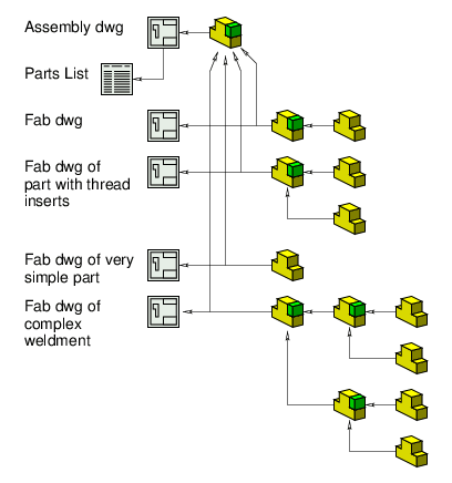
I did the following diagram twenty years ago. I was not aware of SolidWorks' weldment feature, possibly because it had not yet been implemented, but that does not matter. There are any number of reasons and ways to attach a fabrication drawing to an assembly model.

SolidWorks_wi7w8g.png

This is how SolidWorks looks to me. I was designing mostly aluminium parts for devices to be mounted in aircraft, so I needed thread inserts. Unless I was absolutely certain my part would be absolutely simple, I created it as an assembly. For the complex weldment shown, the fabrication drawing would be sent out to a subcontractor. On the BOM (called Parts List) shown, I have no interest in the parts attached to the assembly models linked to my fabrication drawing. There are only four items on my BOM.

My figure does not show a sub-assembly. A standard thing to do with BOMs is to "explode" them, showing the contents of the sub-assemblies. SolidWorks does this, but not very well. Your ERP people will want to do this. If you sent then BOM files which they enter into their database, they can identify which items are sub-assemblies and do the "explode". If they expect the SolidWorks model to do it, you will be restricted in your use of SolidWorks.

--
JHG
 
drawoh,

We currently use Solidworks PDM for managing all CAD files. We have no plans to move away from it, despite the limitations it has at times. I like to think Dassault put their B-Team on PDM development so I'll excuse the poor documentation and confusing terms they use.

What I'm doing is using the generated BOM features built into SW PDM and then using CADLink to push part lists and BOM structure up to Netsuite. See here for their site: We're using CADLink because our quality / mfg team wants the ability to verify changes to metadata before the items get pushed into our ERP database.

Your image above matches how we do configuration / BOM control. It looks like SmarTeam is legacy PDM software for Catia? I would guess it functions quite similarly to SW PDM. The main difference is for purchasing (not for assembly and engineering) we skip the drawing and go straight to a parts list. It allows for our purchasing team to create orders for an entire top level or any of the various subassys if they desire. CAD Link also identifies assys automatically or I can mark assys as "purchased" if I happen to create an assy to mimic a COTS purchase we don't try to order the child parts.

Our techs still have paper in front of them when building and not need SW or E-drawings open all day, I can't even imagine the chaos that would come with that.
 
Status
Not open for further replies.

Part and Inventory Search

Sponsor