mtgski
Automotive
- Jun 12, 2020
- 6
Looking for some insight on a failure of a Stainless Steel Square 1/2" U bolt. 3 1/2" legs and 5 3?4" wide inside. Rated for 5000 pounds capacity with a 20% over factor so 7000 pounds.
Background: this is one of 4 U bolts used on the lifting bunks of a boat hoist that hold up the boat on the lifting frame. Overall capacity of the lift is 4000 pounds ( these U bolts are normally used on a 5000 pound capacity rated boat lift) Boat wet weight is 3500 pounds. The U bolts in questions were brand new last year, used for 5 months on a boat lift in fresh water. The U boats and bunks were removed from one lift to install on another lift this year. On the second day of the boat being loaded on the lift the failure occurred on one of the four U bolts about 45 minutes after the boat was put on the lift.
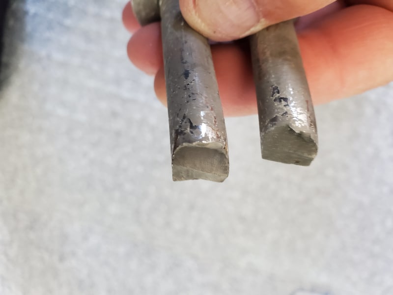
Do you think the tooling mark creases or cuts into the inside corners of the U bolt contributed to the failure? ( since the failure point was at or very near these tooling marks)
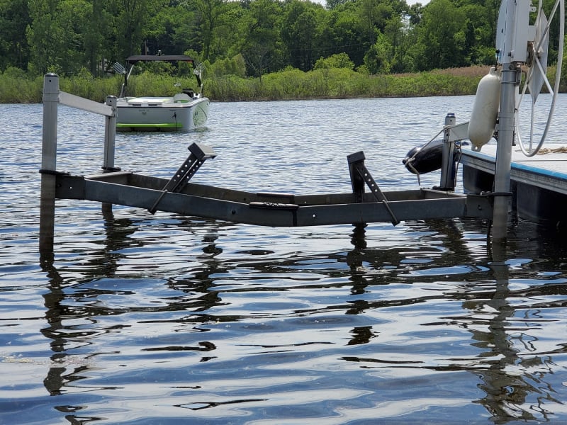
Would the angle of the single U bolt when mounted, with the upper and lower portions not being vertically aligned with each other, have any affect on the load contributing to the failure?
Brand new U bolt
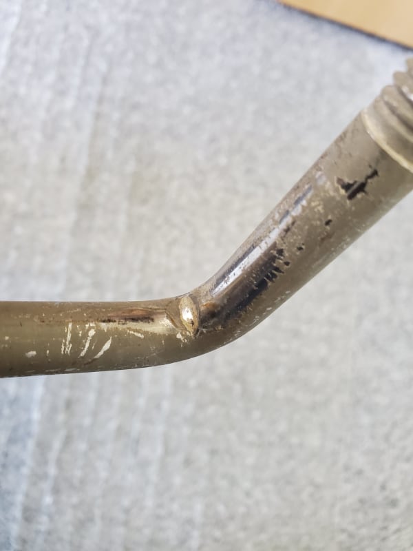
One of the three remaining one year old U bolts
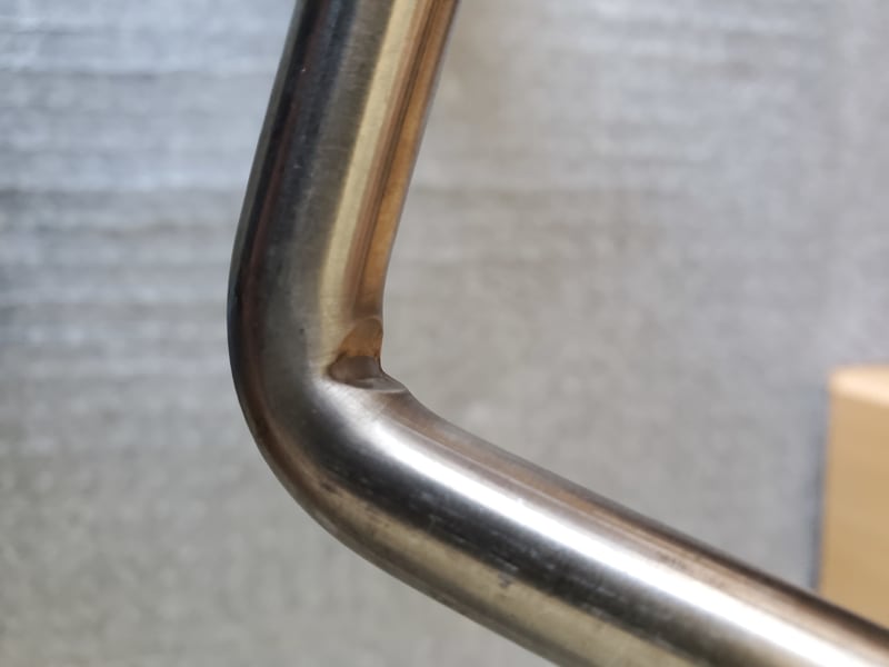
Failed U bolt, inside of bend area
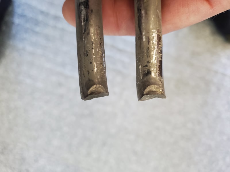
Failed U bolt, outside of bend area
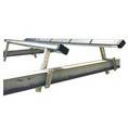
Angle of the lifting bunks, U bolts were offset at an angle about 3 1/2" off center due to 5" cross-member tube and 5 7/8" inside U bolt width.
Background: this is one of 4 U bolts used on the lifting bunks of a boat hoist that hold up the boat on the lifting frame. Overall capacity of the lift is 4000 pounds ( these U bolts are normally used on a 5000 pound capacity rated boat lift) Boat wet weight is 3500 pounds. The U bolts in questions were brand new last year, used for 5 months on a boat lift in fresh water. The U boats and bunks were removed from one lift to install on another lift this year. On the second day of the boat being loaded on the lift the failure occurred on one of the four U bolts about 45 minutes after the boat was put on the lift.
Do you think the tooling mark creases or cuts into the inside corners of the U bolt contributed to the failure? ( since the failure point was at or very near these tooling marks)
Would the angle of the single U bolt when mounted, with the upper and lower portions not being vertically aligned with each other, have any affect on the load contributing to the failure?
Brand new U bolt
One of the three remaining one year old U bolts
Failed U bolt, inside of bend area
Failed U bolt, outside of bend area
Angle of the lifting bunks, U bolts were offset at an angle about 3 1/2" off center due to 5" cross-member tube and 5 7/8" inside U bolt width.