Continue to Site

Eng-Tips is the largest engineering community on the Internet

Intelligent Work Forums for Engineering Professionals

  • Congratulations SSS148 on being selected by the Eng-Tips community for having the most helpful posts in the forums last week. Way to Go!

Stair Embed Question 2

Status
Not open for further replies.

T_Bat

Structural
Jan 9, 2017
213
Another separate stair issue,

I've got embed plates to design for a steel stair framing into the edge of a 12" thick two way slab. I'm acting as delegated engineer so the stair is mine - the slab is by others. This is a relatively long monumental stair 18' rise and 33' run in a single span. In my analysis I've assume pinned-roller for the stringer. However, the stringers will be field welded to embed plates. I know there will be some fixity in real life here regardless of how I design it. If I run my analysis with a fixed condition I get a fairly large moment along with my shear (and axial). We are talking on the order of 70 kip-ft moment, 25 kip vertical shear, and 11 kip axial tension. There is no reasonable way I'm going to get an embed to in the face of the EOR's 12" slab to work for this.

Am I overthinking this? Is a pinned condition here in line with standard practice? If not, what would the EOR have to do to accommodate? Add a concrete beam designed for torsion with anchor reinforcing? If I'm on track with looking at this fixed, I want to know what options we may have...
 
Replies continue below

Recommended for you

I'm thinking of this somewhat analogous to a shear tab. If I'm not mistaken, bolt plowing and plate yielding allow for the rotational ductility of an assumed pin. For my case, what mechanisms will allow for rotation? I doubt I can consider the vertical face of the welded tubes will give me sufficient rotation since it is 5/8" thick.
 
I think I'm going to go pinned and weld the sides of the tube only... I don't feel great about it but there is no way we are going to get full fixity to work here.
 

- I suspect that you haven't gotten much response here because it's a real issue that, by and large, nobody knows how to address without getting crazy. I was hoping that somebody else would chime in so that I could turn a deaf ear to it myself.

- I wouldn't not weld the tops and bottoms of your tubes in a attempt to make yourself a faux pin connection. Firstly, it's BS and the connection between the tubes and embeds will still be rigid for all intents and purposes. Secondly, now you'd be inviting fatigue tearing at the top of the side wall welds which you know perfectly well will be dealing with cyclic moments. The answer to making a weak thing stronger is rarely to make a different strong thing weaker. KootK 53:3-5. Exceptions abound.

- I do like to have a beam at the top of my feature stairs, primarily to stave off vibration issues which can often occur as a result of support flexibility not being accounted for. And torsion capability would be a bonus. Sounds like this is not within your purview, however, so I'll not belabor the point.

- In my heart of hearts, I do not feel as though you have a real world problem here. Firstly, the "rigid" stringer/slab connection will have a some give to it. Secondly, self limited cracking in the slab behind the connection will also result in less moment being transmitted. Thirdly, with your stringers being designed so as not to need rigid connections, I'd expect their stiffness to be such that any moments that developed would be self limiting. This is all ugly but true.

- While I don't know how to rationalize your moments out of existence, I feel that I do know what should be done here from a detailing perspective. I think that you should make the top most anchors of the support embeds generously lengthy DBA's rather than studs. As long as incidental moment doesn't pry the embeds out, I have a hard time seeing things really going south.


I like to debate structural engineering theory -- a lot. If I challenge you on something, know that I'm doing so because I respect your opinion enough to either change it or adopt it.
 
KootK - haha that's what I was thinking... thanks for the responses. I'll have to open up the "good book" and check out that verse. Maybe even look it up in the original language. That will have to wait until Sunday. I suspected your response in point #4 myself but for this load and this particular stair I started getting nervous. I still consider myself relatively green so I can't just wave a hand at this one without some outside opinions. I definitely plan to show the top and bottom of the tube not welded. I thought about doing some extra detailing to the embed to help against pryout. I've run my embed in Profis to get a rough idea of what I need to make it works but shear breakout is an issue.

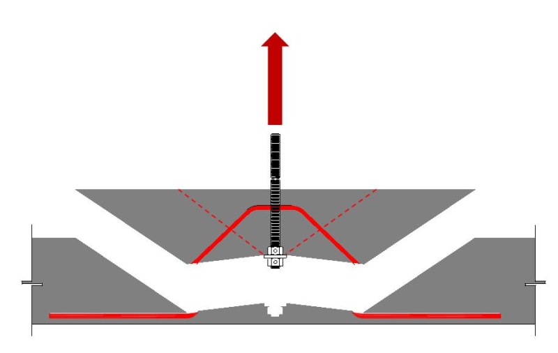
Do you feel the use of long DBA's precludes this failure? I suspect not, based on some other threads you've posted in. If not, I'm going to ask the EOR to take a look and I'd like to suggest a potential solution. I'm toying with using anchor reinforcing. I've only got a 12" thick slab to work with so I can't really hairpin and develop bars back. What about using something similar to the shallow embedment stuff Simpson as developed for embeds in podiums? I've sketched around with how this would affect my break out cone. I haven't fully fleshed it out but just an idea.

anchor4_pkiodg.jpg
 
For embedded plates with really long anchors, I wonder if it would be worth it to use short threaded rod welded to the embedded plate and then use a coupler and threaded rebar. Then you could get as much embeddment as you want without the constructability issues.
 
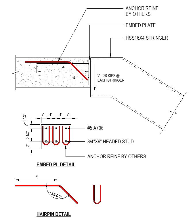
How long is too long? I planned on providing the top bar development length of the of the rebar (likely #5's). Attached is a quick and dirty sketch of the hairpins I'm thinking about. The goal is to tie the bottom anchor back and up. Similar to the Simpson shallow embed stuff - the idea is that the diagonal portion of the hairpin acts as a tie and then a strut can form near the bend back to horizontal. Does that make any logical sense?
 
 https://files.engineering.com/getfile.aspx?folder=996e26e6-ad12-4967-a57c-795e56e4fbb1&file=Embed_PL.pdf
This is the setup I'm going to propose to the EOR. I'd like for them to give me the anchor reinforcing they need before I have to get my client to provide some welded hairpins. Any comments are welcome.

PROPOSED_EMBED_ijfuv4.jpg
 
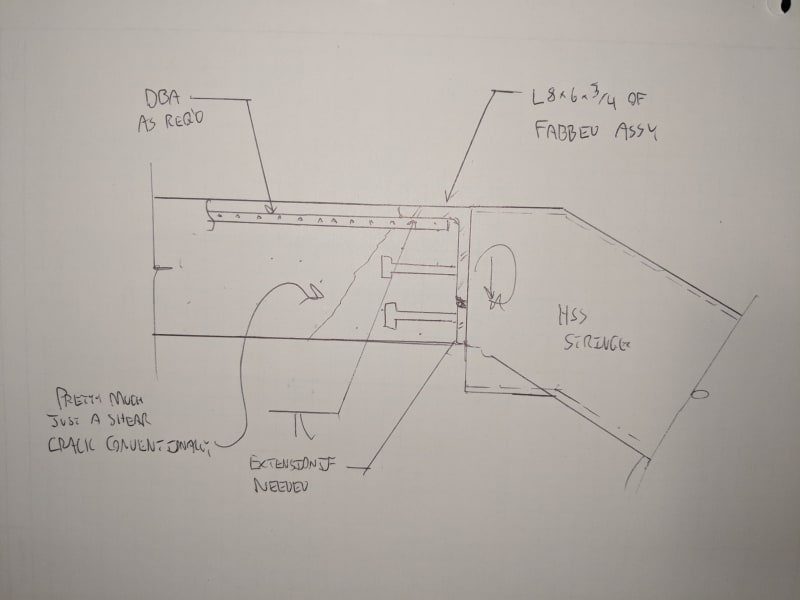
Firstly, I'm terribly sorry for not getting back to this sooner. I've had this sketch sitting on my desk for a while now I'm afraid. While it's surely too late to incorporate any further suggestions, this is still an interesting problem and I'm curious to know how things landed. Here are some thoughts on your solution and the one that I've proposed below.

- Obviously, mine only works if the horizontal angle leg can be tolerated visually.

- Something I like about mine is that it takes the location of shear deliver up about as high in the slab as it is possible for it to get. If this cannot be made to work, I would characterize the problem as a slab design shortcoming rather than a connection design short coming.

- Both of our solutions should produce ductile flexural load failures which I feel is good. I'd be tempted to further lap some longer bars onto the DBA's.

- I don't love the hairpins for a few reasons.

a) might be tough to predict just what the governing shear crack will be.

b) at best, you're dragging the shear up too the top of the hairpins which my detail also does handily.

c) the hairpins are useless until a good sized concrete shear crack develops. are we comfortable with that implication at service load levels?

d) will there be concrete crushing in the knuckle of the hairpins?

e) will you be delivering a shear load to the hairpins that will result in dowel crushing at the point of application?

I acknowledge that these issues may be for the EOR to sort out. Additionally, I'm not overly familiar with the podium anchorage business so there may well be answers there that I don't know about.

c01_jhp7li.jpg


I like to debate structural engineering theory -- a lot. If I challenge you on something, know that I'm doing so because I respect your opinion enough to either change it or adopt it.
 
Thanks KootK. This is still "out there". I sent the earlier sketch through to the EOR to illustrate the issues. I definitely like your detail more. As far as item's d) & e) I'm not sure exactly how to validate these. I assume you have to look at some strut and tie stuff? I'm pretty much a noob as it relates to STM but I'm definitely interested since this seems to be where the art meets science.
 
OP said:
I assume you have to look at some strut and tie stuff?

Yeah. You cold either do curved bar node STM or utilize the provisions of some non-NA codes. I wound't do either of those things really though. I'd detail the connection to avoid having to drag rebar tension around corners. With regard to my detail, depending on how the numbers shook out, I might also add vertical stiffeners to the angle.

I like to debate structural engineering theory -- a lot. If I challenge you on something, know that I'm doing so because I respect your opinion enough to either change it or adopt it.
 
I think we are going to go to the underside of the slab. We are going to extend the stringer back to get it away from the edges. Pretty much eliminates the issues previously discussed. Thanks for the help. I'll try to post a picture when it's done.
 
Status
Not open for further replies.

Part and Inventory Search

Sponsor