Continue to Site

Eng-Tips is the largest engineering community on the Internet

Intelligent Work Forums for Engineering Professionals

  • Congratulations GregLocock on being selected by the Eng-Tips community for having the most helpful posts in the forums last week. Way to Go!

Stair Stringer Beam Uplift Reaction 7

Status
Not open for further replies.

struggle67

Structural
Mar 29, 2013
116
Hi Everyone,

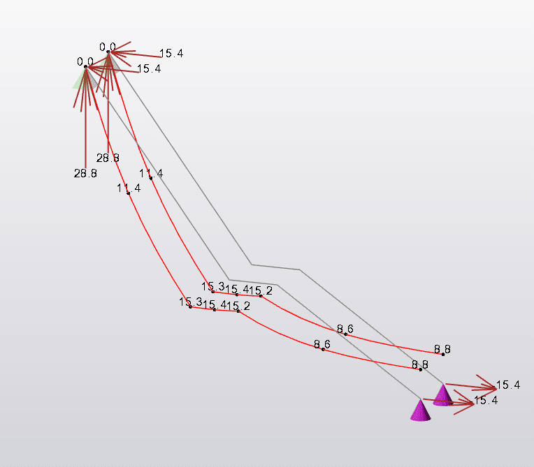
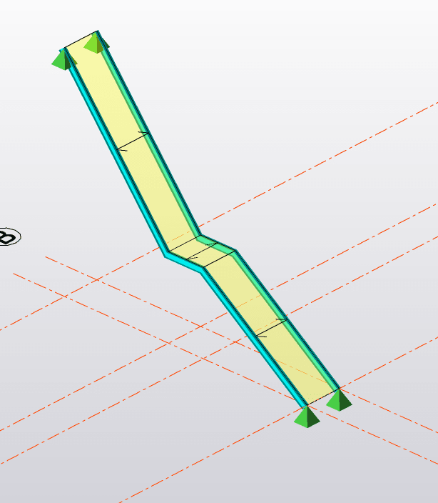
It is my first-time designing stair stringer beams. My model is as shown below. I have upward reactions at the bottom supports and downward reactions at the top supports. At first, I thought that something is wrong with my model so I sent my model to the software support team. They told me that my model is correct and the uplift reactions at the bottom supports are due to the slanting profile of the stringer beam.

I always thought that stair design is similar to one-span simply support design. Why are the reactions uplift? How do I analyze/derive to get those uplift forces? Can't figure out. And the bending moment at the centre of the stringer beam is also zero.
Capture_kfycje.png


Thanks.
 
Replies continue below

Recommended for you

I disagree. I think there is either something wrong with your model or your loading is applied in the wrong direction.

Lean a ladder against a wall. The base of it won’t float up in the air.

Can you post an image of your overall deflected shape?
 
Could you be getting uplift because you have it pinned pinned? Either the top, or the bottom should be considered a roller in the horizontal direction.
 
Based on the image, there should be no uplift. As MIS noted, check your model loading.

Rather than think climate change and the corona virus as science, think of it as the wrath of God. Feel any better?

-Dik
 
Are you reaction vectors pointing up at the bottom and down at the top (for the vertical direction)? If you have pinned both the top and bottom, you probably will get tension at the top and compression at the bottom. You need to release the gravity degree of freedom at the top and your stairs will act like columns. I bet if you look at the axial force diagram in your output it will go from tension to compression (like two triangles).

I typical try to design my stairs as beams and have all the horizontal load go into either the top or bottom supporting memeber, and not have it split between the two levels.
 
where is the load ? somewhere between the two endpoints ? then both reactions are up (loads are down). how can it be other ?

how is this different to a ladder ? If the ladder overhangs the top, then the load can be outside the two reaction points, and the lower load can be up.
But if the load on the ladder is between the two reaction points, both loads are down. It is a three force body, the three forces make a triangle.

another day in paradise, or is paradise one day closer ?
 
This looks like tekla structural designer, which I use also, and I find very good. I suggest you look at it on paper first.

Of more concern is that a software support team said it was ok!
 
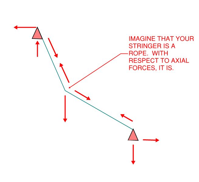
I suspect that your model is behaving as it is because, in the absence of the roller that jayrod12 mentioned, your setup is tending to act like a rope. See the sketch below for a simplified version of something similar.

C01_compag.jpg
 
Thanks for putting my thoughts into a picture Koot. That's what I was envisioning happening.

If I'm being honest, this "mistake" is one of the most common ones I come across when working with other designers. Boundary conditions being incorrectly applied cause models to do some funky things. There have been times where it wasn't caught at the stage the OP is at, but rather once the building is already under construction. When it's caught as early as the OP's, it's less of an issue.
 
This goes back to MIStructE's observation ... if this does indicate incorrect boundary conditions then the guys should've known this.

Can you run the model with a roller support ?

If the stringer is a "rope/cable" (which I highly doubt) then I'd've thought it would react load as ...
all the vertical at the LH end (although I can see a logic where all the load is at the RH (lower) end ... the stringer working in compression)
then the offset moment (vertical load and reaction) is reacted by a horizontal couple at the two supports.

If I took moments about the lower support I'd likely see the upper support with a horizontal reaction,
then the lower support would react this horizontal and the vertical (applied load).

another day in paradise, or is paradise one day closer ?
 
Struggle67:
You are inducing tension in the stringer because you don’t have rollers in the horiz. direction at the bot. reaction. That’s about what KootK said, in another way. And, that is showing up as an upward force at the bot. reaction, along with a large horiz. force/reaction. Also, cranked beams can do some really funny things when you induce axial loads in them. They can induce moment components opposite of what you would normally expect, through the cranked region.
 
I think you need a roller at the LH support, so that you generate only horizontal reaction here.

Won't a roller on the RH make the stairs fall over (if they were a ladder) ?
With only a vertical reaction at the RH, then you could only have vertical at the LH too (equilibrium) ... but not very real.

another day in paradise, or is paradise one day closer ?
 
Hi

Thank you so much, everyone

I run my model with one roller support. It looks fine now & reactions seem reasonable (no more uplift).

KootK,

Thanks for the sketch. Now I can envision what happened with my previous model.

I understand that it is not logical to have uplift at bottom support but is it totally wrong to do pinned-pinned conditions or it is still correct but I will just see weird results/reactions. I am just curious because my actual bolted connections at both ends will have some degree of horizontal restraint.

 
Remember that idealized support conditions have infinite rigidity and strength, even “pinned” connections.

Just a little flexibility at the connection changes the nature of the structure’s action and reactions. Your connections likely will have some inherent flexibility.

You might also check that your forces are applied about the global and not local axes. Many times this does not make a difference unless the beams are rotated or sloped.
 
Look at the deflection at the roller. If it's a tiny deflection, then the model is reasonable. If it's a larger deflection, then you might need to put some amount of fixity in there. The tricky part is deciding what is tiny and what is large. That will depend on how things are connected and what the two supporting points are.
 
As an aside, the two flights are at different angles, the top one looks very steep. I’d get the architect to double check this is what he wants.. A change in flight angle, even if for some reason intentional, will look like a mistake.

If the riser heights change as a result its probably non compliant anyway depending on your part of the world.
 
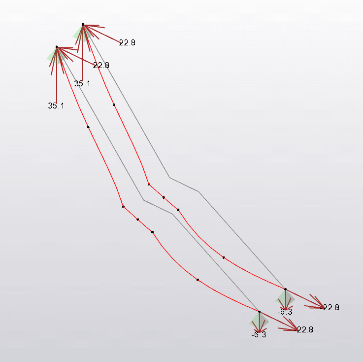
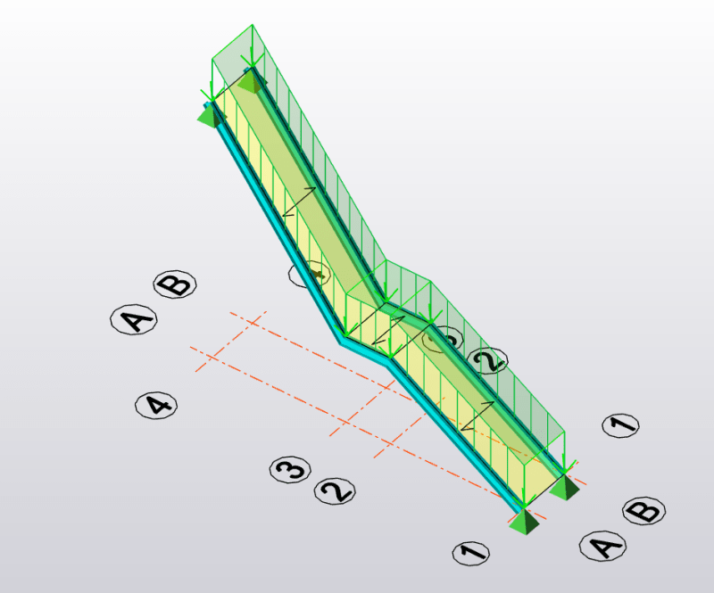
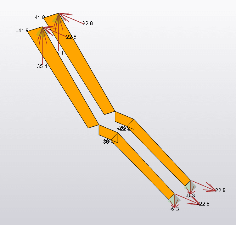
OK.. I stand corrected! I've modelled this (ballpark!) using the same software and get the same anomaly. As you can see below, both stringers are in tension so I'm inclined to go with Koots rope theory. Interestingly, the last image below indicates the same model but I've removed the vertical support element at the base - so the bottom defies physics and floats 8.8mm up in the air...which I don't believe is realistic. If it is, then I'm going to make a fortune showing this trick off at Hogwarts school of magic. Any thoughts?

image_phwqct.png


image_x8gymx.png


image_vg1roj.png


image_ort80p.png
 
I disagree that this should be modelled with a roller support. Unless your connection behaves like a roller then it you are being disingenuous to model it with a roller support.

(Sure we make many simplifying assumptions in our analysis but this should not be one when we can so easily model it otherwise.)
 
@human909, but a pinned support is as much a simplification as the roller. the pinned-pinned constraint over-constrains the beam as the two end points are not allowed to translate, as noted above even by a tiny amount.

if pinned-pinned predicts uplift at the lower support, then I say this is Wrong. if pinned-roller gives more believable results then this is definitely Better.

the most correct FEA would have a finite stiffness constraint at both ends, a flexible pinned connection if you will, which will permit tiny deflections. But this is "unnecessarily" complicated for a stair stringer, where modelling as a "cable" is a "gross" simplification, IMHO.

another day in paradise, or is paradise one day closer ?
 
I think the OP should go back to the help (who figured that this was "fine") and educate them !

And good job struggle67 for asking a "simple" question, when the answer didn't sound right.

another day in paradise, or is paradise one day closer ?
 
Status
Not open for further replies.

Part and Inventory Search

Sponsor