Eng-Tips is the largest engineering community on the Internet

Intelligent Work Forums for Engineering Professionals

Stair Stringer Bolt Design Question

Status
Not open for further replies.

zrck99

Structural
Dec 19, 2014
82
0
0
US
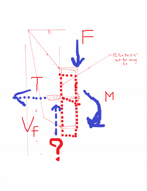
I am putting together a set of calculations to justify the details/design that the a steel fabricator put together for a very typical office building stair set. They plan to connect stringers to walls with 1/2" diameter wedge bolts at 2'-0" o.c.

I've shown the detail in the attached pdf. My question is, won't gravity loads cause the bolt to rotate at the face of concrete because of the 3" flange width standoff? I assume people do this all the time so I'm just curious if anyone has seen a good justification for it. Some of the other guys in my office suggested adding 3" square metal shims in between the wall and inside face of the channel web. I agree this would add some stiffness but it still looks a little indirect to me...

Any thoughts?

Thanks
 
 https://files.engineering.com/getfile.aspx?folder=edf4e585-e392-499f-af1e-be4f1bb12930&file=20200108104700406.pdf
Replies continue below

Recommended for you

I too like KootK's detail. If the 1/4" gap between the wall and the stringer is a problem (or the alignment with the wall needs to be maintained), you could substitute in a C10x15.3 to bring the stringer back tight to the wall.

Rod Smith, P.E., The artist formerly known as HotRod10
 
JAE's detail is impossible unless you field weld to the plate after. Still like OP's detail the best, for the following reasons: 1. You can oversize the hole in the channel so it's easy to construct, since you only want it bearing on the plate. 2. You can be pretty sure the compression force is going through the bottom flange of the channel, so you're moment is larger than kootks.

Edit: Nvm, I see that for JAE's detail you could just put an opening in the web of the channel and sneak the bolt through.
 
canwestteng,

The OP's idea did not solve the concerns:

1. Rely on shear friction by preload the bolt.
2. If friction is lost, bending will occur in the bolt (the plate and channel built-up will move downward together).

Correct me, if I've missed something.
 
...there's stuff to catch your feet on if your a clod.

That was my concern with the anchors protruding through the face of the channel.

I've seen a few stairs, that I think are similar, where it appeared the anchors were installed with just a clip angle, and the stairs were set down on the anchored clip angles and field welded the clip angles to the bottom flange of the channel.

Rod Smith, P.E., The artist formerly known as HotRod10
 
But, even the original detail could be acceptable, if we are confident that shear friction will be there.

From technical data from Hilti for 1/2" Kiwik Bolt,
Allowable tension is 2575 lbs, with steel - concrete friction coefficient ≅ 0.45,
Shear friction capability = 2575*0.45 = 1158 lbs
Assume 3' wide stair, say load = 200 psf, V = 200*3*2/2 = 600 lbs
Factor of safety = 1158/600 = 1.93
 
I wouldn't be confident in shear strength from friction, though. You're counting on the tips of the flanges against a surface that may or not be smooth enough - especially if it's masonry. Getting it tight to a sloppily built CMU wall that's within "allowable" tolerances would probably require more tension in the bolt than you can reliably expect.

Sure, there's going to be friction and under normal service loads (who takes the stairs, anyway?) the friction may even be what carries the load. But when somebody pulls the fire alarm - yikes.
 
I'm solidly against a shear friction mechanism for this. That requires reliable bolt pretension. Having that executed and verified properly in the field strikes me as problematic.
 
Retired13, per this thread, for steel against hardened concrete, a coefficient of friction of 0.3 to 0.2 would be a more typical value. That was a value for a base plate, but there was some mention that the less contact area there was, the lower the applicable friction value. Given the small contact area provided by the flange tips, I'd be hesitant to use a value higher than 0.2.

Also, I think 3' is fairly narrow for a commercial stairway, isn't it?

Rod Smith, P.E., The artist formerly known as HotRod10
 
I think BridgeSmith raises a very valid point that friction on a couple of flange tips, developed by some indeterminate tension in the bolts, is not a good plan.
There's no way you'd know how much true tension is in those bolts, ever. The anchorage into the concrete, whether expansion or adhesive, can slip a bit, or the modulus of the adhesive could vary, etc. so you'd never know what your flange tip compression truly is.

canwesteng: You are correct - I should have had those welds shown as field welds. Access holes in the channel webs would work but very messy and costly.

 
Rod,

No argument here. Just throwing some numbers to make a quick sense. We are engineers, right? And, that is one reason that shear friction is not reliable, as simple as the friction coefficient couldn't be settled (also, how about a guy spilled a cop of coffee over it, shear friction down to zero?!:).

OP,

I didn't see bolt with length that is applicable to the contractor's detail. If they insist, make sure it is not a threaded rod rather than name brand preassembled bolt.
 
I don't think the holes in channel webs are all the messy. Cut em in the shop on a beam line. On the other hand, field welding will mean working on an AWP, underneath a suspended stringer, plus all the QC, fire watch, touch up paint that goes along with it.
 
What is improvement from the contractor's detail, except enlarged contact surface by adding plate?

20200108152226915_1_001_q6idb9.png
 
retired13 -- building off what Rabbit12 said, I'm more thinking of the flange itself as a moment frame that loads up the plate. You will end up with a prying force from the upper flange to plate connection but you are at least avoiding shear friction entirely. The sketch attached tracks through how I'm thinking the loads work.
 
 https://files.engineering.com/getfile.aspx?folder=6695317a-1a5c-43a3-b246-d5c3db1a9c4f&file=20200108164112155.pdf
Double check your force diagram, as ΣH ‡ 0. (±500 on bolt and lower flange, 0 on upper flange)

In this scenario - utilize plate to generate shear and tension in the bolt, I think your system is much better than the contractor's detail, which solely rely on bolt preload and subsequent shear friction.

Sorry, I withhold my judgement above, since I couldn't convince myself that the lower corner capable of, without doubt, be a pivot point, as it subjects to both compression and sliding (zero restrain in vertical direction). At this time, I've no clue how the induced moment is to be resolved.


Status
Not open for further replies.
Back
Top