Eng-Tips is the largest engineering community on the Internet

Intelligent Work Forums for Engineering Professionals

Stamped Part Flatness Question

Status
Not open for further replies.

T_Helm

Industrial
Jun 16, 2020
2
0
0
US
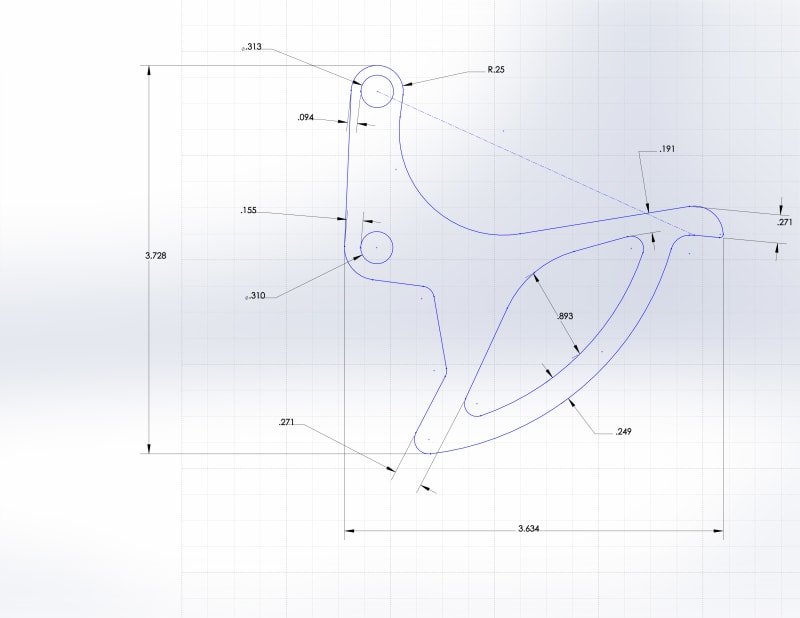
We have inherited a die to stamp out a part which must be flat within 0.010". The part is mild steel at 0.125" thick. I've attached a sketch of the part with some dimensions which show various widths of the material and the proximity of the holes to the edge. The geometry appears to make it extremely difficult to maintain flatness due to the excessive stress that will build up during stamping. The die is not a fineblanking die or a Grip Flow die, but it is a cut and carry with pressure. The material is flat as it enters the die. So, a few questions...

1. Would you take the risk of assuring the flatness spec?
2. What would you do to help maintain flatness and/or regain flatness after stamping?

I appreciate the help.

Part_095_pwt7b5.jpg
 
Replies continue below

Recommended for you

The strip may be flat, but the residual stress in it nearly assure that the stampings won't be.
Stack them with weight on top and stress relieve them. It might help.

= = = = = = = = = = = = = = = = = = = =
P.E. Metallurgy, consulting work welcomed
 
T_Helm:
You said…, “We have inherited a die to stamp out a part which must be flat within 0.010".” In that case, why don’t you ask the people you got the die from, how they used it to meet the final flatness spec? I’ll bet it will make some difference which corner of the piece you start cutting from, although that may be built into the die set, or its initial setup. Did they use some post stamping treatment as suggested by EdStainless, or maybe something other than stress relieving?
 
Thanks, guys.

dhengr, we inherited the die because they have not been receiving the parts within the flatness spec from the previous supplier and we already supply them with other parts that they have been happy with. The die was in poor condition, so we recommended that a new die be built...either a fineblanking die or a grip flow die. I failed to mention in my original post that there are surface finish requirements in the holes and on a portion of the outer edge. The part is cut and carried with shaving punches in the final 2 stations for the surface finish. The customer did not want to pay for a new die, but wanted us to repair the original die. We made the mistake of agreeing to do this. The die is overcrowded and has no idle stations.

Another issue is the method of checking for flatness that the customer is using. I inquired about how they were checking it so we could match, but the response started off with, "He holds an edge down on a surface plate...", so I immediately knew I was going to have a struggle. Not only did I know the method was incorrect to begin with, edge rollover is being pulled into play.

I'm considering sending some sample parts to a 3rd party inspection house to see if the customer will buy off (we're checking flatness pretty consistently at 0.013"-0.016" out of flat right off the die, which I think is very good considering the material and die even though it is still out of spec).
 
T Helm,

0.013" to 0.016" flatness is better than I would have expected right off the die. Do you have any leeway on the part thickness? Maybe a run or two through the time saver could get you even closer.
 
What is the material and what is its condition? Sheet can be flattened different ways, and they each leave different residual stress patterns. Are you doing any leveling as you uncoil?

= = = = = = = = = = = = = = = = = = = =
P.E. Metallurgy, consulting work welcomed
 
Some good ideas from others, but I'd start by backing up a couple steps:

Another issue is the method of checking for flatness that the customer is using. I inquired about how they were checking it so we could match, but the response started off with, "He holds an edge down on a surface plate...", so I immediately knew I was going to have a struggle. Not only did I know the method was incorrect to begin with, edge rollover is being pulled into play.

Ugh. Your customer has likely not heard of GD&T, or functional gaging. Suggest you ask to visit their facility so that you can get an idea of how the part is supposed to function, and what the real tolerances on flatness should be. The trimming and edge finish requirements coming from the shaving dies imply that this thing acts like a trigger blade, with a cam sliding/rolling on the large arc edge surface, so this edge likely needs to be held perpendicular to one or both pivot holes...but I'm just guessing. Building a functional gage (even something as simple as two steel plates held a certain distance apart that the finished item must be able to slip through) that both you and the customer can agree on will get you a lot farther down the road, and hopefully minimize the amount of rework/handwork to produce acceptable parts.
 
Status
Not open for further replies.
Back
Top