Eng-Tips is the largest engineering community on the Internet

Intelligent Work Forums for Engineering Professionals

Standard covering centerline usage without a dimension 3

Status
Not open for further replies.

Stick369

Mechanical
Apr 9, 2010
17
0
0
US
Morning everyone. I'm having difficulty finding a standard the supports the use of centerlines when NOT used for a dimension. Recently the use of centerlines in a side view was challenged, not because it made the drawing unclear but because the individual didn't want to add them and is requesting a standard that say they have to be there. Personal opinions must give way to official standards. If there is no official standard then the company standard is applied, and changed based on the loudest voice.

Our company has required them on prints for years because it was common knowledge to use centerlines when drafting a part. Everyone does agree that centerlines are required when used to dimension a feature. But I cannot find any standard that specifies the requirement for them when used without a dimension.

ASME 14.100, 14.2, 14.24, and 14.3 all cover engineering drawings in some way and speak to the use of centerlines with dimensions. One of them talks about ensuring the drawing is clear and readable. Which lends it to the “how we apply it” argument.

ASME y14.2-20014
Section 4.7 Center lines
[highlight #FCE94F]When used[/highlight], center lines represent axes, center points, or center planes of symmetrical parts and features, bolt
circles, and paths of motion…

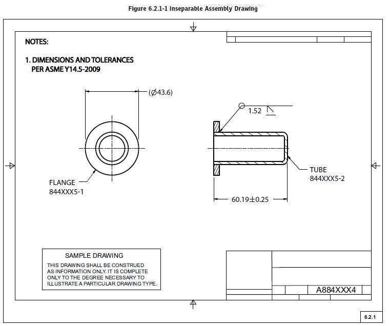
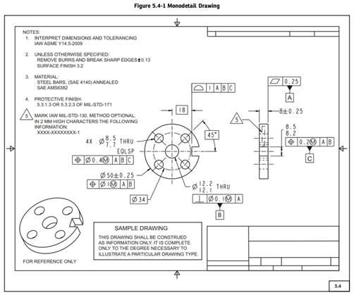
"When used" does not equal "must use". But in almost every example drawing used, in almost every ASME standard, centerlines are shown in side views and they are not use for a dimension. Is it safe to say that if the example drawings in the standards use them, then its a requirement? or is it just an example of "when used" but not required?

ASME y14.24-2000 fig 5.4-1
ASME_Y14.24-2020_fig5-4-1_xftseo.jpg
 
Replies continue below

Recommended for you

Only 150 years of convention suggests using centerlines to depict axes in, for example, side views, as a way to remind the viewer of the drawing that there is a cylindrical surface involved.

It's lttl dffrnt frm th rqrmnt t hv vwls n wrtng. Nt sn a txt tht dmnds t.

If possible add a centerline to their separation papers for trying to make life more difficult for all the other users of the document.
 
"suggest" does not mean required, no matter how long its been suggested. Anything less than a standard that states its requirement does not work. Suggestions, opinions, and "what we've always done" are not factual arguments. The individuals position is that it doesn't help the machinist to have the centerlines. "what does it add?" Is it value added to show a centerline if not dimension to it?

FYI If the vowel is missing, the word is spelled wrong per "standard". Good ol' Merriam-Webster dictionary.
 
There isn't any drawing standard requiring spelling per Webster or any other dictionary.

Tough position to be in. I suggest just going with it. Let the machinist and inspector take care of the problem.
 
I was referring to Webster as being the standard for spelling things properly. Not that Webster is called out in drawing standard.

I choose not to ignore the pile of dirty dishes in the kitchen sink. I prefer to take care of the problem, rather than pass it on for someone else to deal with.
 
As with any drawing, add/omit as needed for the sake of clarity.

Centerlines without dimensions can still add clarity. E.g. Is that a cylindrical hole or a pair of random edges? Does the cylinder on this view line up with the circle in the neighboring view?
 
I agree Tick, but does that mean if a standard allows for them to be omitted. Is it inferred they are required unless omitted for clarity?

Also no single view is used to define a part. The two random edges would be resolved by looking at the front view and seeing a circle.
 
Nhaner,

I agree with TheTick here. The centre lines indicate that the part is round, and they provide something to run dimensions off of. It is pretty clear from your views that the thing is round.

On the specific example you have provided us, I would exclude the hidden lines and the centre lines of the holes. I would maintain the external centre line, because your notch is a symmetric feature.

--
JHG
 
I have a solution. A one page company standard that says centerlines are required to depict axes.

Or a trip to HR to process them out.
 
drawoh - Yes centerline provide something to pull dimensions off of. What I'm asking is what requires the centerline if no dimension is being pulled off of it.
3DDave - Losing good talent because I can't prove them wrong is a ridiculous position. You would seriously fire someone because they disagree with your use of centerlines? I do agree with your solution of documenting the use of centerlines as a company standard, if an industry standard is not available.
Tick - Its a pain for sure.
 
They are not good talent. Good talent says "OK, that's a minor thing." I found that if they struggle with such a little thing the problem increases exponentially over time.
 
the center lines are established by the datums. whether they are there or not. some time in my career the correct standard drafting practices was to add center lines in the drawing. also in the old days datums could be depicted from center lines.
 
well that has happened in my career then something happened, bosses started realizing I made them money by fixing FUBARS and streamlining parts. before the black belt erra
and all the other new 5 s an so on, because I was all ready doing it. in my own way.
What I learned long time ago, "I am now semi retired, 45 years and still going" There are people who criticize just to attack you or cause you ill.
and there are people who actually have constructive advice, need to separate the two. who ever criticized that drawing is very trivial.
 
drawoh - To be clear its not my drawing. That drawing is straight from ASME y14.24-2002, its an example of monodetail part. I referenced it as an example of where the standard shows centerlines being used.

mfgenggear - In the past I've always defaulted to my training as drafter, and to the experience of "seasoned" drafters. Although now it seems you can't put anything on a drawing without having a standard to back it up. Common drafting practices don't count as a standard without ASME or ISO in front of it. We still use centerlines for to applying dimensions according to Y14.5. The disagreement is in the value of a centerline in a view when its not use for a dimension.

Another example from the ASME y14.24-2020. I know what the center lines represent, but what standard says they are required. The two views clearly show their shape. What value do centerlines add in this example? "Because I Said so" doesn't work in todays industry.
ASME_Y14.24-2020_fig6-2-1_h5o2xc.jpg
 
Nhaner

ASME y14.5-2009 Parar 1.4 subpara i & j
(i) A 90° angle applies where center lines and lines
depicting features are shown on a 2D orthographic
drawing at right angles and no angle is specified. See
para. 2.1.1.3.
(j) A90° basic angle applies where center lines of features
in a pattern or surfaces shown at right angles on a
2D orthographic drawing are located or defined by basic
dimensions and no angle is specified. See para. 2.1.1.4.
and
2.1.13 Implied90° Angle. By convention, where center
lines and surfaces of features are depicted on 2D orthographic
engineering draWings intersecting at right angles, a
90° angle is not specified. Implied 90° angles are understood
to apply. The tolerance on these implied 90° angles is the
same as for all other angular features shown on the field of
the drawing governed by general angular tolerance notes
or general tolerance block values. See para 1.4(i).
2.1.1.4 Implied 90° or 0° Basic Angle. Where center
lines and surfaces are depicted on 2D orthographic engineering
drawings intersecting at right angles or parallel
to each other and basic dimensions or geometric tolerances
have been specified, implied 90° or 0° basic angles
are understood to apply. The tolerance on the feature
associated with these implied 90° or 0° basic angles is
provided by feature control frames that govern the
location, orientation, profile, or runout of features. See
paras. 1.40) and (k).
and this has better explanation than I can give

 
Center lines without any purpose other than location definition are not required, though it is considered good practice to show them when they aid in understanding what is being depicted.
Would you really want to make centerlines mandatory for all holes/cylinders/profiles? What if you have a manifold with hundreds of cylindrical passages? It would be hard to see the part in the mess of centerlines.
The purpose of a drawing is to provide a complete, concise definition subject to only one interpretation. Adding every centerline just because the part has circular/cylindrical features is not necessary if not locating or defining something and can be detrimental.
A little common sense goes a long way here.

edit: typo

"Know the rules well, so you can break them effectively."
-Dalai Lama XIV
 
Also, don't base any argument on the figures in the standards except in regards to the principles being explained in the text related to that figure.


"Know the rules well, so you can break them effectively."
-Dalai Lama XIV
 
Status
Not open for further replies.
Back
Top