Continue to Site

Eng-Tips is the largest engineering community on the Internet

Intelligent Work Forums for Engineering Professionals

  • Congratulations KootK on being selected by the Eng-Tips community for having the most helpful posts in the forums last week. Way to Go!

Standard for rounded keys 5

Status
Not open for further replies.

Mannes Karsten

Petroleum
Nov 16, 2017
14
Hi,


I'm unable to find a standard concerning rounded keys.
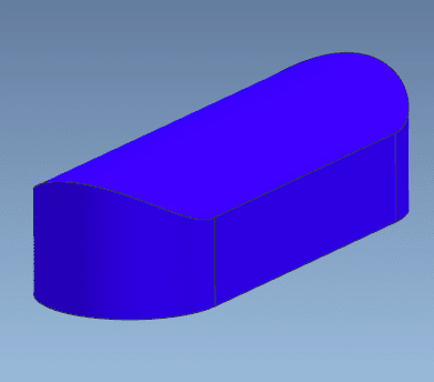
rounded_key_ljmmi8.png


As seen by the image, the top part of the key is also rounded. Meaning the keyway in the hub has a rounded contour instead of a rectangular contour.

I'm reverse engineering a shaft with impellers that have these rounded keyways, but I need to know what the clearance should be between the hub and the top of the key and the rest of the standards.

Anyone got the golden tip?
 
Replies continue below

Recommended for you

I'm having trouble coming up with an answer to this question: "What possible use could there be for a key of that shape?" It seems to defeat the whole purpose of a key, to transmit torque between a shaft and a hub. Can you answer that for me? Curious minds need to know.
 
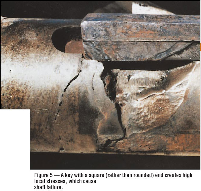
My improvement in this reverse-engineering project would be to eliminate keys and keyways and use shaft locking devices, such as Ringfeder. The rounded key looks to me like a response to a fatigue issue - there is merit in rounding the ends of keys. Don't remember who to credit for the photo.
square_end_key_damage_woos2q.jpg
 
I would surmise that the purpose of the rounded top of the key could be due to very limited space in the hub of the impeller, so the corners of the key were shortened. The rounded ends could fill the shaft keyway, if it were made with an end mill. This would improve balance and eliminate cavities. It could also be used be used to control axial position of the impeller on the shaft, but not likely.
 
We had a liquid ring vacuum pump that experienced two shaft fractures. We redesigned the shaft and changed to round bottom keys to reduce stress concentration. We considered eliminating the keys and using polygon fits. This could be a similar design basis.

Johnny Pellin
 
Thanks for the replies. The reccuring question here of why would you use an oval key is pretty much the same question we have here at the office.

The impellers will be shrink fitted onto the shaft so the transfer of torque won't be totally dependant on the key. These keys don't control the axial placement of the impellers.

The client wants the exact same rotor so that's what we're working towards.
 
My question wasn't about the oval shape key. That is a very common configuration. There are DIN and ANSI standards for that. My comment was about the rounded upper surface. I have never seen that (in 45 years doing this) and do not understand why anyone would do that. It makes no sense to me.
 
I agree with Jboggs : never seen (40 years) and without any sense. Related standards : none, as far as I know
 
Oh, I'm sorry. My native language isn't English. I meant by oval the rounded top of the key.


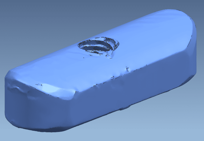
Here the scan that was made:

2019-12-16_14_06_40-Start_hpsayp.png
 
It looks like it has a threaded hole as well. Interesting part - but never seen one like it.

Makes me wonder how the matching slot was made. Plunge EDM seems the most likely, though powder-metal molding could also do this.
 
Is the impeller made of light alloy or plastic? If so the reason might be to avoid creating a stress raiser in the impeller.

Cheers

Greg Locock


New here? Try reading these, they might help FAQ731-376
 
Mannes Karsten: How is this key used? Does it transmit torque? The only other reason I could see for the top rounded surface would be if it were supposed to blend in with the surrounding surfaces of the part to which it is attached. if that is the case, then it might be a replaceable wear item. So, back to my original question - what is it's purpose? What does it do?
 
3DDave,

A slitting saw on a horizontal mill could make the groove much easier than an EDM, assuming a good amount of runout on the end of the groove and axial placement of the key isn't critical.
 
To answer 3DDave's question of how to make a key like that, You mount the key in a keyway on a short piece of shaft and turn it on a lathe. That's another reason for the threaded hole in the key. Again, rounding the top surface of the key allows less metal to be removed from the hub in a location where the effect on hub strength is largest, and it has little effect on the shear strength of the key. Making the keyway in the hub is no different except that a non-standard broach is required. That would make sure that the OEM will most likely get the replacement part business.
 
I know how they make the key. How do they make the matching groove? If the groove was continuous by a broach there's no need for the extraction screw thread - that's needed when the groove has stopped ends.
 
The keyway is cut with an end mill. Thus the rounded ends.
 
The key has a flat bottom against the shaft keyway and a rounded top to fit the the hub keyway.
 
Jboggs; the impellers have pretty decent shrink on them. The bore is at around 100mm. The shrink is 1,5 promille (not sure if that's the correct word in English, but 0/00%).

Main purpose isn't to transfer torque. Seems like more of a back-up than anything else.

Flat bottom key exactly. Hub of the impeller has a rounded keyway in it. Impeller is not from plastic but from 1.4313 material.
It doesn't seem like it's been made this way due to a lack of space in the impeller hub. I've come across impellers with thinner hubs and keyways in them. But it definitely could be an explanation.


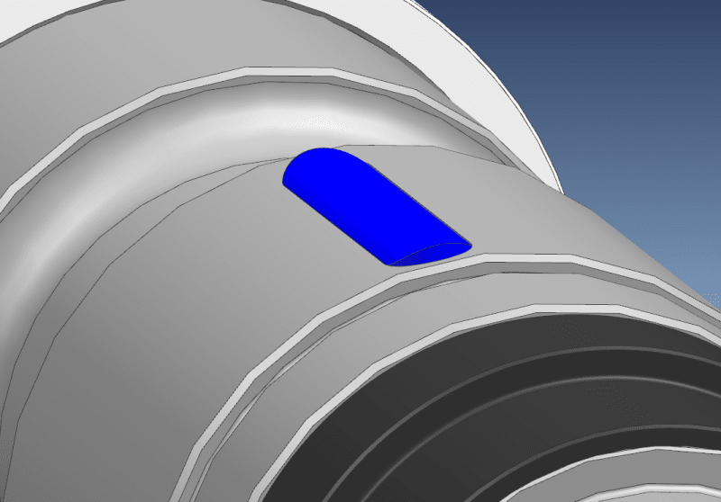
Here is how it sits in the shaft:
shaft_nuzcog.png


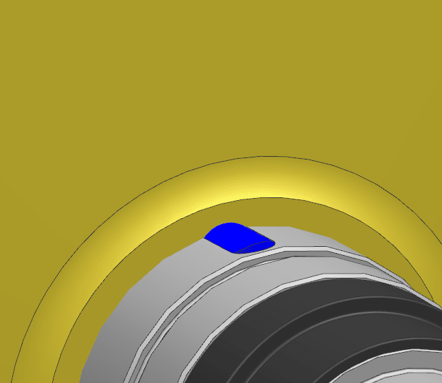
Here is how the impeller looks on top of it: (note that impeller is modelled in a pre-balancing state, so bore isn't accurate)
2019-12-17_08_25_30-Start_ih4o5g.png
 
Status
Not open for further replies.

Part and Inventory Search

Sponsor