Continue to Site

Eng-Tips is the largest engineering community on the Internet

Intelligent Work Forums for Engineering Professionals

  • Congratulations cowski on being selected by the Eng-Tips community for having the most helpful posts in the forums last week. Way to Go!

Steam flow calculation 5

Status
Not open for further replies.

peteng_2020

Petroleum
Mar 2, 2020
3
Hello,

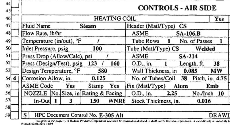
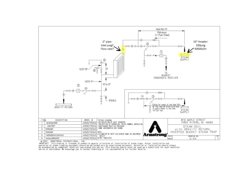
I am trying to determine the conditions of steam flow at the inlet to my steam coil. I have marked up a drawing found online and listed my known and unknown variables to help describe the system I am working with. I began working through the problem this morning, and came to the conclusion that I need one of the following variables to determine the others: the differential pressure, the flow rate through my pipe, or the velocity of the steam. I began calculating the pressure drop throughout the system (ie. for the 10 elbows and the 4 gate valves) but got hung up on calculating the pressure drop for the length of sch. 80 pipe (98 ft.) since I needed to calculate the reynolds number and did not have the flow rate to do so. How can I figure out these variables so I am able to input the flow rate into my steam coil calculation? Or is there a completely different way to break down the problem?

Any help is greatly appreciated!

Armstrong_Steam_Coil_System_gsjwhx.jpg
 
Replies continue below

Recommended for you

The required design heat duty of the steam coil should drive the problem.

Good Luck,
Latexman

 
Unfortunately this particular steam coil was not specifically designed for our application, and was just a standard design. When the designer filled out the data sheet they did not provide flow information or allowable pressure drop. I attached the portion of the data sheet relating to the coil to help provide more information.

Steam_Coil_Data_Sheet_wqdt9a.jpg
 
How much heat you wish your steam coil will exchange with the process fluid?
Is this a future installation or existing? If existing, is it working as intended?

Daniel
Rio de Janeiro - Brazil
 
Incoming steam on your drawing 100#/580F, nominal at 4000 Lb/Hr,
Pipe ID 2.900" (NPS 3 SCH80)
Rd=414583 at max flow
V=128 ft/s

Sounds pretty normal
 
These air heaters are very common. If you can get the manufacturer's literature on the model/size that was installed (i.e. read the nameplate), it will be valuable information. If that vendor is no longer around, match the size to another vendor. There is a good chance you can get the heat duty that way, otherwise you can estimate it, or measure it (set up a test and collect condensate).

Please verify what I think I'm seeing:
The pipe and fittings are 2"?
The coil inlet nozzle is 3"

Is the 100 psi steam saturated or superheated?

Good Luck,
Latexman

 
Is this a future installation or existing? If existing, is it working as intended?
-This is an existing installation intended to heat the ambient air before it contacts finned process tubes sitting just above. When it was operating we had no issues with process tube temperatures, however we encountered a few issues of steam coil tube rupture due to freezing in the coil.​

Please verify what I think I'm seeing:
The pipe and fittings are 2"?
-Yes the pipe, valves, and fittings running from the header to the nozzle is 2". Also, just before the nozzle connection there is a 2"x3" concentric swage.​
The coil inlet nozzle is 3"?
-Yes, sorry I was unclear in my original post. The 2" pipe has a 2"x3" SW Nipple just before its connection to the 3" nozzle.​

Is the 100 psi steam saturated or superheated?
-The 100psi steam is saturated.​
 
My interpretation of OP's post was that the image he attached was just a reference for what his real system is, not the actual system.

I may be wrong though.

Daniel
Rio de Janeiro - Brazil
 
My interpretation was based on the drawing being for an Armstrong Heat Transfer Product (Coils), i.e. air heater. Armstrong makes and sells these.

I could be wrong too!

Good Luck,
Latexman

 
Pressure 100 Psig ( 114.7 Psia )
Process Temperature 340 Deg F (2.1 DegF Superheat)
Ambient Pressure 14.696 Psia ( 0 ft. Above MSL )
Specific Volume 3.906 ft3/Lbm
Isentropic Exponent 1.159
Viscosity 0.016 cP
Pipe I.D. 1.929 inches

Flow 4000 lbm/hr
Pipe Reynolds No. (Rd) 834047
Mean Fluid Velocity (Pipe) 211.6 ft/sec
Line Loss 15.0 psi/100 ft
Friction Factor (f) 0.0197

More or Less
 
It's not going to work this way.

The first red flag is the steam velocity. 200 ft/s is not reasonable for small steam lines. Hopefully, no engineer would have designed it that way.

Secondly, the steam coil cannot consume that much steam. To condense all that steam the coil would have to operate with a heat transfer coefficient of around 1600 BTU/hour.ft2.°F based on the inside area of the tubes. You will be lucky if you get 300 BTU/hour.ft2.°F and 200 would be a better design figure.

The actual steam flow is likely to be in the region of 500 to 700 lb/hour, and the pressure drop through 98 ft of pipe, 10 elbows and 4 gate valves would be 0.4 to 0.7 PSI, with a velocity of less than 40 ft/s.

Katmar Software - AioFlo Pipe Hydraulics

"An undefined problem has an infinite number of solutions"
 
4000 lb/hr is the header's capacity for what I understood.

I agree with katmar that this cannot be the case.

I would start by calculating the heat duty of the steam coil, knowing inlet and outlet air temperatures, area and assuming a U value (engineeringtoolbox suggests a value of 125-150 BTU/hour.ft2.°F, similar to what katmar suggested). With this heat duty, you assume an inlet pressure and iterate a bit to get to your result.

Daniel
Rio de Janeiro - Brazil
 

No question that is excessive steam velocity, but many operatiing plants have even higher operating extremes, during start ups.

We had one 18" steam line, that would regularly exceed 250 ft/s, metered velocity!

Unfortunately all to commonly.

Suspect that the 4000 lb/hr is a startup design number as part of a material balance, and as you point out, the normal operating condition is much lower.


My company design guide for a steam heated air heater is 150 BTU/hr/F/ft2 for a bare area basis or 7.0 BTU/hr/F/ft2 for a finned area basis. katmar, you are on the money!

Good Luck,
Latexman

 
It seems GPSA agrees with your company's design guide, Latexman:

Capturar1_ej205z.png


Daniel
Rio de Janeiro - Brazil
 
Status
Not open for further replies.

Part and Inventory Search

Sponsor