Eng-Tips is the largest engineering community on the Internet

Intelligent Work Forums for Engineering Professionals

Steam flow through spillage in turbine

Status
Not open for further replies.

Superossido93

Industrial
Mar 6, 2020
14
0
0
IT
Hi!
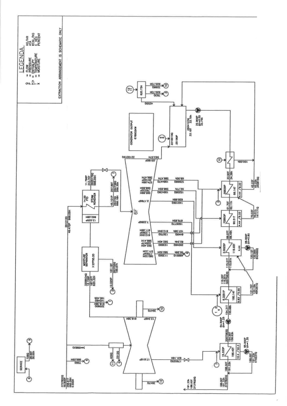
I have a Nucleare power plant operating with a regenerative cycle, that has also spillages in the High Pressure turbine and in the Low pressure turbine(they are 3 LP working in parallel).
Hp and the 3 LP are biflux.
Regarding the 3 LP, I have 6 spillage each, and the problem is that the first one is done between the 1st and 2nd diaphragm on the left side, the second is between the 2nd and 3rd diaphragm on the right side, and the last four are thank god simmetric (2 on the right side and 2 on the left side).
Now, i know the pressure at the inlet of the 3 LP and the overall Steam flow that goes to the 3 LP(i don't know how much flow goes in each LP turbine), I know the Area of the exit of each spillage, and i know at which pressure the flow exit through each spillage. The remaining steam exits the LP going into a condenser (at 0.05 bar), and i know the overrall remaining steam flow and is pressure.

Now the happy part! The 3 LP turbines do not have the same Area of spillage due to calibration, and some are very much bigger.
How can i calculate the steam flow though the spillage?
 
Replies continue below

Recommended for you

A diagram or schematic would really help here along with some pressures, temperatures etc.

Also please define what exactly you mean by "spillage". It's not a term I've come across in this context before.

Remember - More details = better answers
Also: If you get a response it's polite to respond to it.
 
Well, when you do thermal balance on the FWH then you know how much steam it is getting.
Do you think that the values are significantly different from the design?
You should have a fairly good idea of what the total bleed from each turbine is, and the sum of the flows from the FWH end of these should total the same.

= = = = = = = = = = = = = = = = = = = =
P.E. Metallurgy, consulting work welcomed
 
here the link to my dropbox for a bettere resolution of the image
NPP_example_yt3uyp.png


as you can see, I attached the example of heat balance of the power plant. The problem is that it groups all the 3 LP turbines in 1, and I only have the sum
of the steam flowing from the 1st bleed( don't know why they didn't supply the bleed flow from each LP turbine).
But, since I have the pressure of all the heat exchanger with the Feed water, the bleed Area,and the total steam flow and the overall bleed flow from each bleed, I should be able to calculate the bleed flow of each bleed of each LP turbine, right?

UPDATE!

I know that usually the slow in the turbine is proportional to the area, the square root of the pressure, and inversely proportional to the square root of the specific volume. finally i found this file from GE explaining the equation:


at page 11 you can find it in all his glory! Now, I don't know the coefficient of discharge, but that i should easily find it. I don't have the specific volume , but i do have the temperature of each steam bleed, so i can calculate it, and finally i don't have that constant "K". Where do I find it?
 
Since the LPs are on a common shaft most people treat them as a single unit.
But you are correct in that the flows and temps will be slightly different.
The reason that they don't split the bleeds between the LPs is because this creates a lot more piping and the flow imbalances are not consequential in the LPs.
How many FWH do you have and what is the arrangement? Sometimes they try to balance the flow by bleeding steam flow from various LPs to various FWHs. This doesn't exactly balance but it does get close enough.

= = = = = = = = = = = = = = = = = = = =
P.E. Metallurgy, consulting work welcomed
 
EdStainless- Each Lp turbine has their bleed going into a total of 4 FWH ,so they are a total of 12 FWH, 4 for each LP turbine.(there is a "fifth" FWH solely attached to the High pressure bleed,so i donìt consider it for now). I saw for example that the LP turbine named "C" is a little less efficiency, and after his 4 FWH, the feedwater exiting has slightly less temperature than the other 2, so when they combine (they will then continue into the single "fifth" FWH) I will obtain a lower temperature than the one designed.
 
Are the FWH set up 4 in parallel with 3 in series, or is it 3 in parallel with 4 sets in series?
How good of data do you have on the flows and inlet/outlet temps on the FWHs?
These bleed flows are often controlled with simple restrictors, and small shifts on backpressure or wear on the orifice can upset the flow balances.

= = = = = = = = = = = = = = = = = = = =
P.E. Metallurgy, consulting work welcomed
 
3 in parallel with 4 in series.
The image that i send previously was a good estimation of how the plant should work. Is there a way to calculate the separate bleed flows?
 
how do your heat balances on the FWHs work out? Are those good numbers?

= = = = = = = = = = = = = = = = = = = =
P.E. Metallurgy, consulting work welcomed
 
Please understand that the flow in each bleed is not related to the inside area of the bleed pipe. The formula on Page 7 of the GE document (Page 11 of the PDF) discusses the flow through the turbine blade path, not through a bleed pipe.

Bleed flow is a function of the heater performance characteristics, primarily, the Terminal Temperature Difference (TTD) and the Drain Cooler Approach (DCA). Unfortunately, these parameters are not constant for all turbine loads. Bleed pressures in the three LP turbines may vary due to differences in the blade path flow areas in each LP. (Flow area in individual blade rows, rotating and stationary, may vary by +/- 3% to +/- 5%.) In addition, bleed piping arrangement may affect the pressure at the inlet to parallel heaters, associated with each of the three LPs. Differences in the piping from each LP will produce differences in the pressure losses in the bleed piping. Inlet pressure to a heater also affects heater performance.

In addition, the heater performance will vary with the feedwater flow through a particular heater. It is hard to imagine that the feedwater piping arrangements through each of the three LP heater strings are identical. Therefore, temperature leaving the heater string for each LP will not be identical. Also note that plugging of heater tubes may also affect heater performance, if the number of plugged tubes is significant.

Most of the bleed flows in a nuclear cycle are in the wet region of the Mollier diagram. Wet steam flows can only be determined using the radioactive tracer method. See ASME PTC 6, Steam Turbines: Power Test Codes.

As you can see the problem of determining the bleed flow is complex. The good news is that cycle performance software, such as PEPSE (Performance Evaluation of Power System Efficiencies by Curtiss-Wright/Scientech) can be used to model these complexities. The bad news is that the software is expensive. In addition, extensive work is required to define all the cycle components and piping.

Rather than using cycle performance software, I suggest comparing current performance of each heater to historical data for the same heater at the same turbine load (output) condition. You may also want to calculate the feedwater pressure drops through each of the three LP heater strings so you can apportion the feedwater flow through each heater string.

Best of luck!
 
Thank you stgrme, you bled to death my heart. I thought it was possible with pessure and area. Well, it was worth a shot. I will try and see if I can find that program that you mentioned, if not I will do with historical data. Thanks again
 
Status
Not open for further replies.
Back
Top