Eng-Tips is the largest engineering community on the Internet

Intelligent Work Forums for Engineering Professionals

Steam Turbine 1st Wheel Blade Root Crack

Status
Not open for further replies.

fsxn155

Mechanical
Jun 29, 2020
29
0
0
QA
Dear All
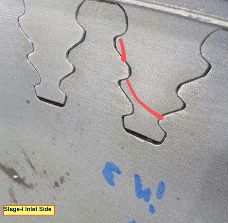
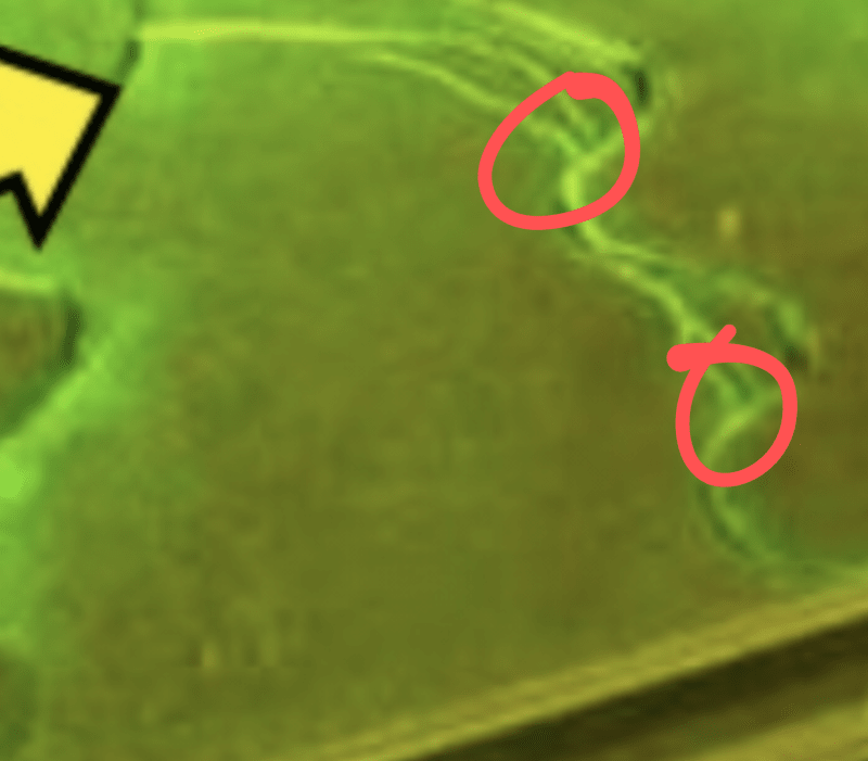
Recently during planned outage of a Steam Turbine, we have observed cracks on the Roots of some Blades in 1st Wheel. The Blade Roots are dovetail design. Turbine is Multi Stage (08 Stages) Extraction/Condensing Impulse Turbine (Rateau Turbine.) Live Steam conditions are 61 barg & 430 Deg Celsius. Extraction is at 10 barg after 3rd Stage

After evaluation of the operating parameters, OEM has attributed the cracks to some events of sudden/sharp Temperature drop measured upstream of TTV. As per OEM rate of Temperature change exceeding 4 Deg Celsius/minute can cause cracks in Blade Dovetail Slots.OEM has asked us to maintain Rate of Temperature drop within 4 Deg Celsius/minute measured at TTV Inlet. I am not understanding the OEM's responde due to following

[ul]
[li]In my understanding Turbine 1st Wheel Blades are exposed to Steam exiting 1st Nozzle. So 1st Wheel Blades are exposed to After 1st Nozzle Pressure and Temperature. As its impulse Stage almost entire 1st stage Pressure Drop (61 barg to 30 barg) will be across 1st Nozzle. For a given change in Inlet Temperature the change in 1st Nozzle Exhaust Temperature will be less (constant Pressure Lines diverge from left to right on Temp. Entropy Diagram). Based on above in my opinion measuring after 1st Stage Temperature will more accurately reflect the Temperature Changes experienced by 1st Stage Blades.[/li]
[li][/li]
[li]In my understanding during Load Changes, Temperature downstream of Governor Valves will vary due to throttling of Governor Valve. OEM has given Extraction & Exhaust Temperature Vs Inlet Steam Flow curves indicating Extraction Temperature change (drop) of 20 deg Celsius as inlet Steam Flow varies from 140 to 160 Ton/Hr (Curve is non linear and tends to flatten as Stem Flow increases). In my understanding there will be similar changes in Temperature of Steam entering 1st Wheel. (Extraction is after 3rd Stage & Extraction Pressure is app. 10 barg.)[/li]

Based on above I am totally confused by OEMs reply. May be I am missing something ?
 
Replies continue below

Recommended for you

I agree with you. I think the manufacturer is probably trying to shift blame for the failure of their design. The drop in temperature seems a very, very unlikely cause of blade root cracks. If the cause was not based on a poor design, then I would consider some other possibilities:

How is the turbine trip tested? Is it a full speed, spinning test? Did the trip test result in operation of the turbine above its maximum design speed? If the trip system is fully electronic, do a single, spinning trip test at reduced speed and all other testing using simulated signals.

How are the blades retained? Does the retention method create a stress concentration of some sort?

Test the failed blade. Could stress corrosion cracking be the issue? This is more likely for cracks in the wheel than the blade. But, if your steam quality is poor, it might be possible to have SCC in the blade root.

Johnny Pellin
 
JJP covered the big ones, the other thing that comes to mind is heating rate. Since this will heat the blades much faster than the disc it could cause undue stress on the dovetails.
When looking for corrosion you need to be very careful. What materials (alloys) are you dealing with? You are looking for very small amounts (ppm or less) of Cl and or S (these two being the most likely).

= = = = = = = = = = = = = = = = = = = =
P.E. Metallurgy, consulting work welcomed
 
Dear JJ & EdStainless
Thanks for your useful inputs

The Turbine has Electronic Overspeed Trip System and there is no Mechanical Overspeed Trip. Trip Test is done at reduced speed by simulation.

The Blades are retained by Shrouds at Outer Dia (group of 06 Blades in one Shroud Segment).

Chemical Analysis on one of the damaged blades indicated presence of Cl by 0.1% by Wt & S by 0.2% by Wt. However on another Healthy Blade S found to be below 0.001 % by Wt & no Cl Found. Therefore presence of S & Cl above allowable limit on damaged blade has been attributed to cleaning compounds being used for NDT.

OEM has proposed improved design which we are evaluating. But considering the installation base of similar machines at our facility, implementing that will take time and we will have to live with existing design. Therefore if we intend to monitor Temperature Changes on 1st Stage Blades what should be the measuring point
Inlet Temperature upstream of TTV or After 1st Stage Temperature (downstream of 1st Nozzle). Right now we only monitor After 1st Stage Pressure. There is no provision for after 1st Stage Temperature measurement

 
Dear JJ
Regarding you point about about Blade Retention, I believe you are referring to retention in Axial direction. Physically looking at the blades I am unable to find any mechanism for retention in Axial Direction (like twist locks in GE heavy Duty Gas Turbines). I need to further check this. (I have no experience of Blades Removal on Steam Turbine Rotor)
 
Does the crack propagate across a gap? What NDT has been done?

Screenshot_20210616-214817_qliftj.png
 
I hope I didn't condescend. I've never seen a crack propagate like that and will be curious to see what th other users say.

Edit: I see it now in your MT picture. There are two separate initiation sites and the cracks started in the circled areas.

Screenshot_20210616-234619_p74vmz.png
 
For this style of blade, the retention is probably some sort of pin between blades or under blades (or both). This is the blade retention for a similar turbine in our plant. A FEA would be needed to evaluate the stress concentration resulting from the retaining pins.

Capture_kzvvlj.jpg


The FEA on our blades shows higher stresses close to the possible initiation sites for your cracks.

Capture_ucubeg.jpg


Johnny Pellin
 
You should still have a failed blade tested by a metallurgical lab for crack characteristics and fracture surface morphology. This should allow you to confirm or reject the possibility of SCC. I would not rely on the presence or absence of chlorides or sulfides as an indicator.

Johnny Pellin
 
Dear JJ

First of all many thanks for useful info regarding Axial Retention methodology for blades in this type of Turbines.
02 out of 05 failed blades have been tested at metallurgical lab. I have still not received the details but as per initial feedback, lab results didn't find any evidence of SCC.
As I mentioned before, there 06 blades in each shroud group. Out of 05 damaged Blades 4 are first in respective Shroud Groups when counting in direction of rotation and 5th one is 2nd. Based on this OEM has proposed double Shroud design with overlapping shrouds to eliminate "Shroud End Blade".
As per OEM the failure mode is rapid temperature change causing blades to shrink and pulled towards centre of Shroud Group
 
I have never seen Rateau blades with shrouds in the first stage of an impulse turbine. I would expect at least one Curtis stage and I would expect the Rateau blades to be un-shrouded. Seems like a strange design. They sometimes use tie wires between adjacent blades to reduce blade flutter, but a full shroud seems very strange.

Johnny Pellin
 
The OEM’s concern about a rapid drop in temperature upstream of the TTV may be related to a loss of fire in the boiler and/or a carryover of water with the steam (a water induction). Entry of “cooler” steam into the turbine can result in high stresses due to thermal shock. Carryover of water can cause impact damage. In the case of water entry, I would expect damage to the first stage nozzles if they are air foil type nozzles. In addition, the first stage (wheel) blades might also be damaged by the impact of slugs of water.

You are correct that first stage blades are exposed to the steam conditions exiting the first stage nozzles. The pressure at the inlet to these nozzles can vary depending on the position of each of the turbine’s governor (control) valves. Therefore, the pressure exiting each nozzle group (group of nozzles associated with a particular control valve) is a combination of pressure drop across the valve and pressure drop across the nozzles. Since the opening of the control valves is normally sequential, steam temperature exiting from each nozzle group will vary, perhaps by 15 deg-K to 25 deg-K.

Temperature measured after the 1st Stage will reflect a temperature reduction due to work done by the first stage blades. This temperature reduction can be significant a lower inlet steam flows where most of the work is done by the first stage. Therefore, temperature measured after the first stage will not accurately reflect the temperature entering the first stage blades.

In my experience, the cracks in the roots of the first stage blades, shown in your photos, are not uncommon for the side-entry (axial-entry) style of blade root used in large utility type turbines. Cracks in the first stage wheels have also occurred. First stage blades are exposed to high vibratory stresses due to the high velocities exiting the first stage nozzles. These stresses can be amplified by entry to, and exit from, the arc of admission (arc of active nozzle groups). Also from my experience, radial entry, and triple foil units with finger root fastened to the wheel with axial pins, have performed better in control stage applications.

As to Johnny Pellin’s comment about shrouds used in Rateau stages, shrouds, particularly in control stage applications, are used to reduce leakage around the blades and may also be helpful in reducing vibratory stresses.

Best of luck!
 
Dear stgrme

Many thanks for extremely useful reply. Your idea about Boiler trip and cracks in 1st Nozzle is absolutely correct.
For sake of clarity of situation, please note the Turbine under discussion is Mechanical Drive Turbine in Petrochemical Plant with normal Power of 40-45 MW, 8 Stage, Condensing and Extraction (after 3rd Stage). The Turbine receives Steam from a common Header. The Steam Header is fed by one Waste heat Boiler/HRSG which receives Flue Gas from exhaust of Primary Reformer/Furnace as well as an Auxiliary Gas Fired Boiler.
There had been Inlet Temperature Drops to subject Turbine in the events Furnace feeding Flue Gas to Waste Heat Boiler is Tripped.

Please refer to the attached pdf Annex-I for Trends of Turbine Parameters Live & Extraction Steam Parameters, RPM, Wheel Chamber Pressures, Exhaust Pressure etc. during a most recent incident. The Inlet & Extraction Temperatures have reached Saturation point. Extraction Temperature reading is only reliable when Inlet flow is 195 Ton/Hr or more as otherwise with Extraction Valve Full open Extraction flow will be 0

In Annex-II & Annex-III I have attached Startup Trends of 6 stage Once Through Back Pressure Turbine. The Inlet Steam Pressure & Temperature of this Turbine are same as that of Extraction/Condensing Turbine under discussion. Similarly Exhaust Steam Pressure of this Back Pressure Turbine is same as Extraction Pressure of Condensing Turbine under discussion.
I have not used Transient Data of Extraction Condensing Turbine under discussion as Extraction Temperature Reading is not reliable due to 0 Extraction Flow during Startup

From the Startup data of the Back Pressure Turbine, it can be seen that the there are Temperature changes which are more rapid and nearly same in magnitude as those experienced by the Extraction/Condensing Turbine under discussion.

So I am not under standing how significant contributor are the Boiler Trip events when it comes to Turbine Blade Stress. Keeping Water damage aside as we Blade Airfoils were OK with no erosion of leading or trailing edges though we had found cracks in 1st Nozzle as pointed out by you.

Actually the dilemma is we have to decide b/w following

[ul]
[li]Inlet Temperature changes during Boiler trip are the major cause of cracks and if we are able to eliminate/minimize Inlet Temperature Changes during Boiler Trips there will not be the problem of 1st Stage Blade Root Cracks[/li]
[li]Some design change is required in Blades to make them more robust to withstand Mechanical Stresses. OEM by the way has proposed a design change recommending to change to double shroud design with overlapping shroud segments thereby eliminating Shroud Group End Blades[/li]
[/ul]


I would also take this opportunity to clear my understanding of following points from experts on this forum

[ol ]
[li]In an multistage, multivalve Turbine say 04 Governor Valves, if 2 out of 4 Governor Valves are full open and 3rd Valve is partially open, increasing opening of 3r Valve will increase Pressure upstream of 3rd Nozzle Box as well as 1st Wheel Chamber Pressure which is same on downstream of all Nozzle Boxes. This implies Pressure Ratio across the 1st and 2nd Nozzle Boxes (with up stream Governor Valves full open) will decrease as 3rd Governor Valve will open. Steam Flow through Ist & 2nd Nozzle Boxes will remain unaffected as Pressure Ratio remains above critical Pressure Ratio ? If this is the case this means for every multistage multivalve Turbine Pressure Ratio across control stage should be above critical Pressure Ratio ?[/li]
[li]Changing Governor Valve Position varies Pressure Ratio across all downstream Stages which implies for full admission stages (after control stages) upstream Pressure of each Stage will change more than downstream Pressure ?[/li]
[li]Change in Pressure Ratio resulting from Governor Valve movement will be same for all stages or likely to be more for control Stage[/li]
[/ol]
 
 https://files.engineering.com/getfile.aspx?folder=105de5d2-87f2-4160-8343-58c00a1d7fd4&file=Steam_Turbine_Parameters_Trends.pdf
In my first response I noted that a rapid temperature drop produces thermal shock. Rapid cooling results in high thermal stresses at the surface of the metal bathed by the “cool” steam.

In response to your dilemma:
• I don’t know your plant processes, so I don’t know if there is any way to control the drop in main steam temperature within the limit specified by the OEM. If the temperature drop cannot be controlled within this limit, I believe that the only safe alternative may be to trip both steam turbines (Extraction-Condensing and Backpressure). I would suggest the trip be initiated by the loss of heat source to the Primary Reformer/Furnace to ensure the earliest TTV closure.

• An overlapping double shroud may reduce stresses in the blade root. I don’t by how much. I suggest that you ask the OEM to provide you with the stress levels in the blade root area relative to the allowable stress for the original design and for the new shroud design. I am also concerned with the potential for damage to the blade grooves in the Control Stage wheel (disc). I suggest that you ask the OEM for an inspection program for the grooves in the wheel. You might want to hire a consultant to make an independent assessment of the damage to the blade roots, of the inspection program for the wheel and of the proposed repair.

Clarifications:
1. I don’t have access to the turbine design information so I don’t know at what Governor Valve opening the pressure drop across the Control Stage will be less than critical. However, in the first bullet item of your first post, you cited a First Stage pressure drop from 61 barg to 30 barg. The absolute pressures for this operating condition are approx. 62 bara and 31 bara, so a pressure ratio of 0.50, potentially the minimum pressure ratio for critical flow. For any Governor Valve opening beyond this point, flow through the Control Stage may be less than critical.

2. For any full admission stage (non-Control Stage), operating in straight condensing mode (no Extraction Pressure control), the inlet pressure at that stage is a function of the flow through the stage group (group between extractions) and is essentially linear except at low flows. Therefore, the pressure ratio is essentially constant. For stages upstream of the extraction, the absolute pressure at the inlet to the stage will be different and non-linear when the Extraction Pressure is being controlled.

3. The pressure ratio across a Control Stage varies much more than any other stage. At start-up, the pressure ratio approaches infinity with essentially zero downstream pressure.

Also remember there is a second Control Stage downstream of the Extraction Control Valves. The same relationships apply to the stages beyond the second Control Stage except for the last stage in the turbine.

Best of luck!
 
Status
Not open for further replies.
Back
Top