Continue to Site

Eng-Tips is the largest engineering community on the Internet

Intelligent Work Forums for Engineering Professionals

  • Congratulations cowski on being selected by the Eng-Tips community for having the most helpful posts in the forums last week. Way to Go!

Steam Vent Control Valve - Reaction Force Calculation

Pavan Kumar

Chemical
Aug 27, 2019
397
Hi All,

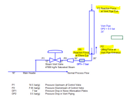
I want to calculate the reaction force at the elbow exit(F1) and vent pipe exit(F3) for a Steam Vent Control Valve that has been sized to vent excess steam pressure. It has been sized to vent the full boiler load as the worst-case. At this flow (47000 kk/hr), the pressure upstream of the control valve is 14.5 bar(g) and the pressure downstream of the control valve is 7.62 bar(g) ( 0.5 bar in the piping (assumed) and 7.12 bar in the noise attenuation plates given by the Control valve vendor). I am trying to calculate the reaction force using ASME B31.1(2020) Non Mandatory Appendix II -Section II-2.2.1 gives a methodology for a PSV with an Elbow discharge ( with and without vent pipe).

I want calculate the following for my application and want to know if the method given in ASME B31.1 can be applied or not. If not what is the correct way. My system sketch is copied below.
A Thread on this forum discussed a little bit on this topic but for a PSV with silencer in the downstream. If this can be applied I want to know how to correctly estimate the equivalent length for the silencer.

https://www.eng-tips.com/threads/silencer-sizing-and-psv-outlet-piping.200194/

1. Pressure at Control Valve Exit,. P1a
2. Pressure at Elbow Exit, P1
3. Velocity at Elbow Exit, V1
4. Reaction Force at Elbow Exit, F1
5. Pressure at Vent Pipe Exit, P3
6. Reaction Force at Vent Pipe Exit, F3
7. Lifting Force at Vent Pipe Entrance, F2.

1744057474874.png


Thanks and Regards,
Pavan Kumar
 

Attachments

  • 1744056167222.png
    1744056167222.png
    29.1 KB · Views: 1
Replies continue below

Recommended for you

Your data are obscure.

1. Is it a closed discharge or open discharge (i.e., whether the discharge elbow is decoupled from the vent pipe)?
2. How did you arrive at P2 = 7.65 bar(g)? This should be calculated after calculating pressure drops across all equipment, fittings, and piping downstream of CV under the given flow condition(unless it is directly controlled by the CV).
3. How did you arrive at DP1=7 bar? Is it by experiment? If so, what was the velocity?
4. DP2=0.5 bar; what is the basis?

Even though a vent valve is not strictly a safety valve, the underlying physics are similar. We can imagine that the vent valve is maintaining a certain pressure inside the main header under certain operating conditions (start-up, etc.).

As per clause II 1.1-Scope, of Non-Mandatory Appendix II, B31.1
"For convenience, however, the overpressure protection device is generally referred to as a safety valve..."

So, in theory, the B31.1 rules can be applied, but with precautions.
 
The silencer may be much better in the vertical section as at the moment it seems to me to be simply adding more lever arm and hence moment on the flange connection. However you don't really show where any of your supports are going to be placed. If you have no supports then this looks to me to be a very poor design which will break off the moment you start pouring steam through it.

It's really a momentum force calculation on the elbow which is forcing the steam to change direction, plus a bit from the end cap force at the base of the silencor.

For momentum it's really mass x velocity?
 
The method is B31.1 is applicable. The method in B31.1 assumes that there is sonic velocity at the discharge of the elbow pipe at point 1 and that there is also sonic velocity in the vent pipe exist at point 3. In your case there is not sonic velocity developed for the flowrate and pipe sizes involved but you can still use the B31.1 equations with this understanding, with results as follows:

1. Pressure at Control Valve Exit,. P1a

I assume the control valve vendor performed calculations for their acoustical plates pressure drop based on basically assuming atmospheric pressure existing downstream. With subsonic flow existing at the elbow discharge P1 will actually be atmospheric 14.7 psia or 0 psig gauge pressure. The B31.1, P1 equation actually predicts about 3.75 psia but since this is below atmospheric then the actual pressure will be atmospheric at P1.

The pressure drop in 20" sch 30 pipe is negligible at 0.63 psi per 100 feet at flowrate so basically there will be atmospheric pressure at the outlet of the acoustical plates plus about 0.63 psi drop assuming 100 feet of equivalent of 20" with elbow. The vendor has calculated 7.12 bar drop across the plates therefore I assume is correct so the pressure upstream of the plates is 7.12*14.5 + 0.63 = 104 psig. There is a little more pressure loss in the 12"x20" increaser with will raise the pressure slightly but there is an increase in velocity to the 12" which will decrease the pressure so balance with added friction loss so pressure at 12" valve outlet will be about 104 psig.

2. Pressure at Elbow Exit, P1

P1 is 0 psig since sub-sonic flow exists of about 500 ft/sec max - sonic flow is approximately 1626 ft/sec or 1551 ft/sec predicted by V1 equation B31.1. Therefore there is no P1 pressure force at the elbow exist.

3. Velocity at Elbow Exit, V1

I calculate the actual maximum velocity is 500 ft/sec. The B31.1 equation assumes sonic velocity so V1 = 1551 in accordance with the B31.1 equation.

4. Reaction Force at Elbow Exit, F1

Considering velocity V1 per B31.1 of 1551 ft/sec the momentum force on elbow WV/g = 1384 # x 2 (impact Factor) = 2768 # = F1

P1 pressure force = 0

5. Pressure at Vent Pipe Exit, P3

P3 is also atmospheric since V3 is also subsonic.

6. Reaction Force at Vent Pipe Exit, F3

7. Lifting Force at Vent Pipe Entrance, F2.

The net force on the vent pipe is negligible and can be considered zero. The pressure drop in the 24" sch 30 vent pipe is about 0.25 psi per 100 feet. Therefore there is negligible pressure drop in the vent pipe. Since there is negligible pressure drop in the vent pipe then P3 is approximately P2 and V3 is approximately V2. Therefore F3 approximately balances with F2 and net force on vent pipe is negligible.
 
Last edited:
Your data are obscure.

1. Is it a closed discharge or open discharge (i.e., whether the discharge elbow is decoupled from the vent pipe)?
2. How did you arrive at P2 = 7.65 bar(g)? This should be calculated after calculating pressure drops across all equipment, fittings, and piping downstream of CV under the given flow condition(unless it is directly controlled by the CV).
3. How did you arrive at DP1=7 bar? Is it by experiment? If so, what was the velocity?
4. DP2=0.5 bar; what is the basis?

Even though a vent valve is not strictly a safety valve, the underlying physics are similar. We can imagine that the vent valve is maintaining a certain pressure inside the main header under certain operating conditions (start-up, etc.).

As per clause II 1.1-Scope, of Non-Mandatory Appendix II, B31.1
"For convenience, however, the overpressure protection device is generally referred to as a safety valve..."

So, in theory, the B31.1 rules can be applied, but with precautions.
Hi Goutam,

Apologize for the delay in getting back to you. Here are my responses.

1. It is open discharge with a vent pipe is located on a standard drip pan elbow arrangement.
2. The pressure drop in the silencer plates is 7.12 bar and I have assumed 0.5 bar for the piping. So it totals to 7.62 bar(g).
3. Answered above.
4. It is just an assumption. I will calculate it for accurate basis.

Yes I agree with you that vent piping design can be done using the basis provided in ASME B31.1 but the formulae cannot be used as there are derived for sonic velocity as Snickster notes below.

Thanks and Regards,
Pavan Kumar
 
The silencer may be much better in the vertical section as at the moment it seems to me to be simply adding more lever arm and hence moment on the flange connection. However you don't really show where any of your supports are going to be placed. If you have no supports then this looks to me to be a very poor design which will break off the moment you start pouring steam through it.

It's really a momentum force calculation on the elbow which is forcing the steam to change direction, plus a bit from the end cap force at the base of the silencor.

For momentum it's really mass x velocity?
Hi LI,

The silencer is to provided immediately downstream of the Control valve vendor, please see snapshot below for my model. The supports are being designed based on pipe stress calculations based on my input on the reaction force.

1744383171148.png


Thanks and Regards,
Pavan Kumar
 
The method is B31.1 is applicable. The method in B31.1 assumes that there is sonic velocity at the discharge of the elbow pipe at point 1 and that there is also sonic velocity in the vent pipe exist at point 3. In your case there is not sonic velocity developed for the flowrate and pipe sizes involved but you can still use the B31.1 equations with this understanding, with results as follows:

1. Pressure at Control Valve Exit,. P1a

I assume the control valve vendor performed calculations for their acoustical plates pressure drop based on basically assuming atmospheric pressure existing downstream. With subsonic flow existing at the elbow discharge P1 will actually be atmospheric 14.7 psia or 0 psig gauge pressure. The B31.1, P1 equation actually predicts about 3.75 psia but since this is below atmospheric then the actual pressure will be atmospheric at P1.

The pressure drop in 20" sch 30 pipe is negligible at 0.63 psi per 100 feet at flowrate so basically there will be atmospheric pressure at the outlet of the acoustical plates plus about 0.63 psi drop assuming 100 feet of equivalent of 20" with elbow. The vendor has calculated 7.12 bar drop across the plates therefore I assume is correct so the pressure upstream of the plates is 7.12*14.5 + 0.63 = 104 psig. There is a little more pressure loss in the 12"x20" increaser with will raise the pressure slightly but there is an increase in velocity to the 12" which will decrease the pressure so balance with added friction loss so pressure at 12" valve outlet will be about 104 psig.

2. Pressure at Elbow Exit, P1

P1 is 0 psig since sub-sonic flow exists of about 500 ft/sec max - sonic flow is approximately 1626 ft/sec or 1551 ft/sec predicted by V1 equation B31.1. Therefore there is no P1 pressure force at the elbow exist.

3. Velocity at Elbow Exit, V1

I calculate the actual maximum velocity is 500 ft/sec. The B31.1 equation assumes sonic velocity so V1 = 1551 in accordance with the B31.1 equation.

4. Reaction Force at Elbow Exit, F1

Considering velocity V1 per B31.1 of 1551 ft/sec the momentum force on elbow WV/g = 1384 # x 2 (impact Factor) = 2768 # = F1

P1 pressure force = 0

5. Pressure at Vent Pipe Exit, P3

P3 is also atmospheric since V3 is also subsonic.

6. Reaction Force at Vent Pipe Exit, F3

7. Lifting Force at Vent Pipe Entrance, F2.

The net force on the vent pipe is negligible and can be considered zero. The pressure drop in the 24" sch 30 vent pipe is about 0.25 psi per 100 feet. Therefore there is negligible pressure drop in the vent pipe. Since there is negligible pressure drop in the vent pipe then P3 is approximately P2 and V3 is approximately V2. Therefore F3 approximately balances with F2 and net force on vent pipe is negligible.
Hi Snickster,

I thank you very much for providing me a direction for the calculations. I will do these calculations and get back to you with results.

The momentum force should use the actual velocity not sonic velocity correct?. Can this be done?

Thank You.

Pavan Kumar
 
Last edited:
Yes I would like to see your results. The B31.1 calculations is a cookbook method that takes the real method using the ideal gas equation and puts into a cookbook formula. I will show you the real equations using the ideal gas equations and how the B31.1 calculations are derived from these equation.

I am not that familiar with the B31.1 equations for I never used them. I used the ideal gas equations to do the analysis. However from what I see and calculate, the B31.1 equation for velocity assumes sonic velocity based on a derivation I just performed of the B31.1 equations from the ideal gas equations. I will show you how it works after you post your results.
 
Last edited:
The B31.1 force calculation does not require the flow to be supersonic.

However, as per the same B 31.1 document, the designer has the responsibility to ensure that the results are conservative.

There is a major deviation of your system from the usual safety valve configuration. The approximate safety valve size (calculated as per Spirax Sarco document with 14.5 barg set pressure, 47000 kg/h flow) is 4". So you can see the difference and the huge size compared to the usual safety valve size, which results in such a low pressure at the discharge elbow exit.

In all probability, your system will have a shockwave after CV, probably at 12"x20" interface or after the silencer, depending on the silencer details and calculation.

However, the calculation of forces after you get the pressures and velocities can follow B31.1 method.

A simplified conservative method suggested is as follows:

-Assume a normal shock(or a succession of normal shocks) after the silencer where the pressure drops to 0 barg.
-Calculate the velocity in the discharge elbow.
-To prevent blowback, change the open discharge system to a closed discharge system.
-Calculate forces based on pressures and velocities. The pressure force is to be applied at the silencer exit.
-Calculate support forces and moments at supports and the CV tap-off point on the main header.
 

Part and Inventory Search

Sponsor