Continue to Site

Eng-Tips is the largest engineering community on the Internet

Intelligent Work Forums for Engineering Professionals

  • Congratulations SSS148 on being selected by the Eng-Tips community for having the most helpful posts in the forums last week. Way to Go!

Steel Beam Cantilever on Wood Wall

Status
Not open for further replies.

T_Bat

Structural
Jan 9, 2017
213
Hey everyone,

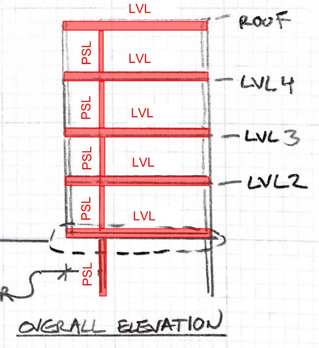
I have a (4) story wood hotel I am designing in normal winds and SDC B. The second floor cantilevers out about 4 feet and then continues up to the roof. We have steel beams on steel columns to support the cantilever but the contractor was surprised at the amount of steel we have shown. I'm wondering it it's reasonable to eliminate one of the columns and have the beam bear on top of the wood wall. There will be welded threaded studs attaching the sill and top plates to the beam.

The other complication is this condition occurs at shear walls - I'm hoping to use my steel integral with the shear panels. I've attached some figures for clarity. The issues I see are as follows:

1. How "braced" is this beam in reality? We have wood floor trusses hung off of the top flange and wood diaphragm only.
2. How big of a deal is is shrinkage here? Obviously the potion over the column is going nowhere but what happens away from the column when the sill and top plates shrink?
3. Is there a scenario where a wood column (PSL or the like) could be subbed in? Admittedly I haven't run numbers on this yet.

Thanks for your help!
 
 http://files.engineering.com/getfile.aspx?folder=7de6c106-d911-4e67-b497-64fa8d42a1a9&file=Proposed_Cantilver.pdf
Replies continue below

Recommended for you

1) I would provide bolt holes in a base plate and thru-bolt through the wall top plates. It would be as braced as any other connection. Make sure your nailer on the top flange is fastened adequately.
2) Over 4 storeys it can be significant. Have you take this into account with the the rest of the project? i.e. elevator shafts, stair shafts, etc. You would've had this issue whether you had a steel column at each end of the beam or not.
3) most definitely there are lots of scenarios where this is possible. Is it not possible for those outer W21 beams to be wood? it would probably make the contractor feel better as well. Even if you needed one at each floor and roof level they may prefer that to a bunch of W21s.
 
Thanks for the input. I've provided responses for you items:

1) The nailer will be attached with welded threaded studs to the top flange. Stud spacing is to be TBD based on what I need for lateral loads. I'm not sure what you mean - are you talking about a steel baseplate with trough bolts?
2) Shafts are going to be wood framed actually. I see what you mean that this would have been an issue even with two steel posts. The wood under the beam would want to shrink away from the bottom flange. There is really only one floor of shrinkage below the beam. The shrinkage from above the beam would have little impact on this steel framing - is that correct?
3) Cant make the outer beam wood - what you don't see is brick veneer that we are trying to support. That's part of the reason for the steel.
 
1) I do mean a steel baseplate with thru-bolts for the beam connection at the interior wall. The baseplate would be wide enough that the thru-bolts clear the wood column you'll need to bury in the wall.
2) That is correct. Generally I run with about 1/4" per floor of shrinkage, but if you go to a wood column in the interior bearing wall, I don't see it being too large of an issue. The shrinkage above is not a concern as theoretically all the wood framing above should shrink at the same rate. You could minimize the shrinkage for the first floor even more by going to engineered lumber plates. These exhibit negligible shrinkage. The studs themselves can still be dimensional lumber as in the long direction the shrinkage is also negligible.
3) Makes sense. I agree you've got to go with steel at that point. Or talk the architect into a self adhered brick veneer on the cantilevered area to lower the demand.
 
T_bat said:
How "braced" is this beam in reality? We have wood floor trusses hung off of the top flange and wood diaphragm only.

Not at all except locally at the column and the cantilever tip since your important flange compression is at the bottom.

I'm with your contractor. Seems like you could eliminate all that steel and probably make things simpler for yourself as well.

- lose the W25x55 by using cantilevered LVL at each level.
- lose the W21x44 by using a relief angle for brick support every other story or so.

c03_ar4awo.jpg


I like to debate structural engineering theory -- a lot. If I challenge you on something, know that I'm doing so because I respect your opinion enough to either change it or adopt it.
 
I like Koot's proposal. You could likely limit the LVL beams to only in level 2 and 4. Beam in 4 supports 4th and roof, beam in 2 supports 3rd and 2nd. I think Koot gave you an extra floor in his sketch.
 
I never like cantilevering LVL's with high sustained loads. They seem to sag more than they should. There also seems like alot of chance for wood bearing/crushing issues - even with the PSL posts.
I prefer the steel design with steel columns.
 
This is getting too fancy for my liking but would address any cantilever creep issues. Wall panel supplier might not love you. Better to be feared anyhow though.

You want a stiff cantilever no matter what with the joists running this direction.

c03_pwq4h7.jpg


I like to debate structural engineering theory -- a lot. If I challenge you on something, know that I'm doing so because I respect your opinion enough to either change it or adopt it.
 
I would just make the PSL column the same width as the stud wall, provide thick wood sheathing with blocking and lots of nails in the cantilevered portions. This would stiffen up that area and turn it into a combination of plywood box beams to compliment the LVL. Likely cheaper and easier than putting in a diagonal and would act the same.
 
T_Bat:
I agree with XR250. It used to be frowned upon to support masonry on wood framing. But, I suppose that if you codify and FEA the hell out of it, anything goes these days. Can you go 4 or 5 stories high without a shelf angle? There are some fairly heavy loads involved, and they are permanent and very susceptible to deflections, not transient like some of the LL and lateral loads, so deflection, settlement and creep become more important. It never ceases to amaze me that the contractor is allowed to bitch (even given the time of day) about any savings on one or two 9' stl. columns under a 21 or 24" WF beam, on a brick veneered, 5 story bldg., with 4 stories of wood framing above the stl. beam level. These stl. bms. and cols. have the potential of fairly clean connection details, and are to be replaced with wood cols., marginally less expensive than the stl. cols., but with more complicated structural analysis, connections and detailing. What a savings, working hard to make the lower level framed system a less consistent framing system, making the soft story, softer. I don’t know why they don’t just do their own Structural Engineering, think of all they could save then, without any disagreement. You Structural Engineers can make any stupid idea work, just don’t back charge for your extra time and potential liability. I suppose when the contractor made this great savings request/proposal/demand, he and the Arch. were busy selecting the colors for the brick and all the granite counter tops and marble tile. They’ve pretty well honed in on the gold gilding (pink vs. yellow gold) and the finish on all the gold hardware. Next they are going to look for structural system savings so they can afford to try to make the floor plan work.
 
Great info - I just did a similar layout with LVL's at each floor for a nearly identical plan without brick and it was very tough to get them to work although we made it happen. If you add the brick load at the tip of the cantilever stacking up for (4) levels it seems like it would be extremely difficult to get the wood to work - mostly from accumulation of loads at the bearing point. I would also need to drill through the middle of the LVL's for my shear wall hold downs. So if I had a three ply LVL I feel I could only count on two plies since I'm effectively drilling out the middle. I would feel better with the steel personally and the contractor has expected steel - he just didn't expect as much I as showed. I feel if I can eliminate almost half the columns and foundations I can do a lot to get them closer to their budget.

As far as beam bracing I agree I could (and should) justify a brace point at the column. The tip of the cantilever should be braced at by the beam framing in the side and for cantilevers I thought the top flange was critical for bracing.

Thanks everyone!
 
T Bat said:
I thought the top flange was critical for bracing.

- you want to brace the top/tension flange over the cantilever but, really, I doubt that you need anything there other than the tip & column bracing.

- you want to brace the bottom/compression flange over the backs span.

I like to debate structural engineering theory -- a lot. If I challenge you on something, know that I'm doing so because I respect your opinion enough to either change it or adopt it.
 
KootK - that makes sense. I misunderstood your comments.I guess I may need to look more closely at the length behind the cantilever before the point of inflection.

[EDIT - Fixed some inexcusable typos]
 
Status
Not open for further replies.

Part and Inventory Search

Sponsor