Continue to Site

Eng-Tips is the largest engineering community on the Internet

Intelligent Work Forums for Engineering Professionals

  • Congratulations KootK on being selected by the Eng-Tips community for having the most helpful posts in the forums last week. Way to Go!

Steel Beam Connection on Top of Reinforced Concrete Column

Status
Not open for further replies.

n39

Civil/Environmental
Jan 16, 2023
38
Picture1_ughccv.png


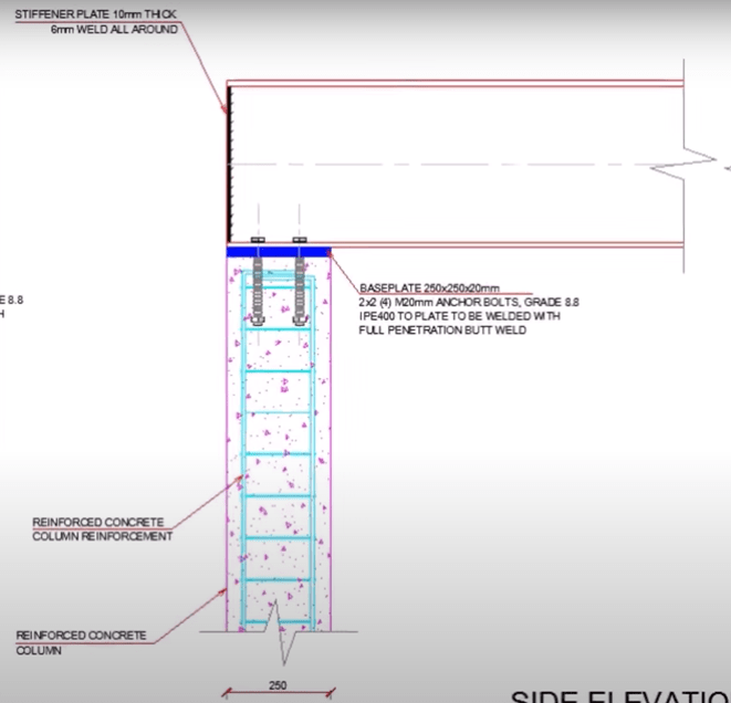
Hi, I found this image on google and was wondering if anybody can provide me with some example of the calculation or a book/journal that can explain it. How was he able to come up with that thickness and numbers of bolts, etc.
HoHow do you design this type of connection?

A calculation sample or a book or a journal is preferable. Thank you in advanced
 
Replies continue below

Recommended for you

Not me, but some individual out there or somewhere in this world, there must be exist a connection like the image above. And there is no harm in gaining more knowledge
 
Well, if that person asked the question, I would tell him that his connection is cumbersome, expensive, and unnecessary.
 
I do not agree to hokie66. This is a very common connection that you see or design. You can easily find many examples or calculations for this. This is just first principles nothing more.
Check steel bearing, steel lateral torsional buckling, steel plate strength, anhcorage strength, concrete and do those according to the code..
 
AISC 360 has some great calculations. This is an American standard, but still has some meaningful design examples and calculations.
1. Part 14 goes through beam bearing plate sizing
2. The stiffener plates on the end are determined through Spec section J.10.

Concrete Anchors are through ACI 318 chapter 17 in the US. Hilti Profis software can do a lot of this for you, once you have a basic understanding of the principles and what you are doing.

I would like to echo loti_eng that this is a pretty common connection in my realm.
 
I would not be surprised if hokie is objecting to the full penetration weld spec. I have seen parts of this detail without that spec. We would use an embed plate with studs or A706 bars instead of the bolted connection.

PCI will likely have some examples of this.
 
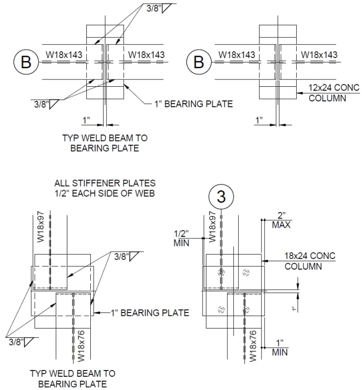
This was from a recent project... The baseplates were secured by headed studs... The EOR wanted the weld all around the beam at the baseplate... tricky to do with the close proximity of the ends. Flanges for the beams can be in excess of 1".

Clipboard01_rucdga.jpg


-----*****-----
So strange to see the singularity approaching while the entire planet is rapidly turning into a hellscape. -John Coates

-Dik
 
OP said:
How was he able to come up with that thickness and numbers of bolts, etc.

For what it's worth, everything in that detail looks completely boiler plate to me. You certainly can design something like this but my money says we're looking at a standard detail here that mostly just gets regurgitated without a lot of thought.
 
If there's no uplift or shear, the anchor bolts are subjected to 10 kips (44.5 kN) shear total where I practice. It's kind of an integrity requirement.
 
My objections to the detail are:
1) The plate is the same size as the concrete column, a very skinny little thing.
2) As others have said, a full penetration weld makes no sense. How would you do it between flange and bearing plate? What is it far? The bolts go through the beam flange.
3) If this is an attempt at a moment connection, it doesn't pass the smell test. That size beam is going to easily overpower the column.
4) What are 4 bolts for? 2 bolts centrally located in the little column would make more sense.
5) Embedment of the bolts, combined with the reinforcement, looks insufficient. Why are the column bars cogged at the top? Much better for the bolts to extend further, with straight column bars. The way it is shown, placement of concrete through the assembly at the top would be unnecessarily challenging.
6) The stiffener location at the extreme end of the beam does little as a stiffener.
 

Is that common?

-----*****-----
So strange to see the singularity approaching while the entire planet is rapidly turning into a hellscape. -John Coates

-Dik
 
@dik Probably not. It's an obscure bit of code and I can't find it now, but it's enforced in New York City for columns. 2% of axial load (if I recall correctly) or 10 kips has to be restrained laterally where the beam connects to the column, in both directions.
 
Thanks... I've always connected them for, "That looks strong enough." I've not had an actual value to use... 2%... friction covers that. For the details I submitted... the beam reactions required by the EOR are about 400K combined (it'll never see anywhere near that... based on 67% of UDL loading... and big beams with short spans.) EOR wanted them welded all around... I submitted based on welding to flange sides only. The spec'd well has a capacity of about 90K... lots... just because I can't weld to the back edge.

-----*****-----
So strange to see the singularity approaching while the entire planet is rapidly turning into a hellscape. -John Coates

-Dik
 
Status
Not open for further replies.

Part and Inventory Search

Sponsor