Continue to Site

Eng-Tips is the largest engineering community on the Internet

Intelligent Work Forums for Engineering Professionals

  • Congratulations KootK on being selected by the Eng-Tips community for having the most helpful posts in the forums last week. Way to Go!

Steel Beam Strengthening 1

Status
Not open for further replies.

Aytacoglu

Civil/Environmental
Dec 4, 2023
38
Hi All,

I am currently working on a steelwork strengthening project where the aim is to install repair plates to the existing steel beams at a cable shaft.

This is a historic structure and over time, the steel beams have severely corroded causing section losses to the flanges and the web of the beams.

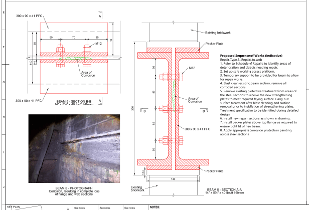
The client proposed a conceptual design where they require installation of new plates to strengthen the steel beams. One of the proposals is to install a channel (PFC) section to the web of the existing I-section at either end, and connect with M12 bolts at the web only.

I am trying to come up with a design for this and trying to carry out some calculations to check the bolts. I have attached the detailed images below for reference.

My question is regarding the requirement for bolts at the top flange. Although the bolts are provided on the web, no bolts have been proposed for the top or bottom flanges. Please find some of my questions that I am looking for answers below:

- If we are doing this repair at the mid-span where we have the maximum moment, are the bolts at the web will be sufficient? Or we
- How can we know whether the design forces will be transferred to the beam using the bolts at the web only?
- How do we know whether you require bolts at the top or bottom flanges and whether there is a calculation that can be done to check whether only web bolts are sufficient to transfer the forces?
- Is this related to Shear Flow calculation?

It would be great if someone can help me on this. I have attached some details below for illustration.
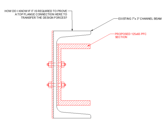
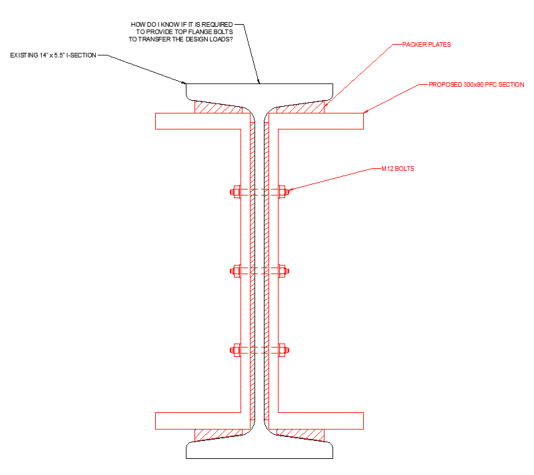
Proposed_design_of_Beam_2_with_question_dslv8e.png

Proposed_design_of_Beam_1_with_question_cqigic.png

Conceptual_Design_of_Beam_1_with_repair_plates_ery53f.png
 
Replies continue below

Recommended for you

If all of the components of the reinforced section will have their shear center at a common, vertical elevation, then the shear flow problem becomes greatly simplified and all that is required is that the fasteners be capable of delivering the required vertical shear to each component of the cross section. This is similar to how things are often treated in multi-ply wood member design if you are familiar with that.
 
Thank you so much for your response @KootK.

When you say all is require is that the fasteners have to be checked against vertical shear to each component of the cross section, do you mean you need to check it for the flanges as well?

All I want to understand is whether those bolts connected to the web would be sufficient, or would it require additional bolts connected to the flanges in order to transfer the forces?

Also assuming that the reinforced section is symmetrical, the shear center will be common, as shown in the figures above?

It would be great if you could assist me on these and I would appreciate any references or literature that may help me with this.

Thanks!
 
OP said:
When you say all is require is that the fasteners have to be checked against vertical shear to each component of the cross section, do you mean you need to check it for the flanges as well?

No, you only need to transfer vertical shear between the independent, non-contiguous pieces to match the share of load that each piece is assumed to resist. You can transfer that shear through whatever part of the cross section you like but stiffness considerations will make transfer through the webs a logical choice.

OP said:
ll I want to understand is whether those bolts connected to the web would be sufficient, or would it require additional bolts connected to the flanges in order to transfer the forces?

Web fastening alone will be sufficient so long as the centroids of the components aligned, as I described earlier.

OP said:
Also assuming that the reinforced section is symmetrical, the shear center will be common, as shown in the figures above?

Yes.

OP said:
It would be great if you could assist me on these and I would appreciate any references or literature that may help me with this.

Shear flow and VQ/It still apply to this. It's simply that, when you work through the numbers, the problem simplifies as I've described. I don't know of a reference that speaks to this particular aspect of shear flow design. By all means, if you doubt my conclusion you'd do well to run through the calculation once yourself to convince yourself of its validity. I promise to only be mildly offended.
 
When it comes to fasteners, another consideration in addition to shear flow is local bracing of the parts of the cross section that would be in compression and not have nearby fasteners to stabilize them.
 
@KootK thanks.

The idea of the design is to increase the section modulus to give a higher bending/shear resistance. That's why the proposal is to overplate.

In that case, the way you describe it above, there may not be a need to provide packer plates either, no? Because in the images I sent you can see that there are packer plates installed both between the top and bottom flange, in order to make contact with the flanges of the existing beam.

If the shear flow can be transferred to the new steel sections, then there may not be a need for the packers in this case?

One final question is that, is this calculation going to be similar with a Beam Splice connection? Where the plates and bolts can be checked against the design forces?

Thank you so much again for your time and help KootK really appreciate it!
 
OP said:
In that case, the way you describe it above, there may not be a need to provide packer plates either, no?

There's no need for the packer plates with respect to shear flow. That said, they may offer benefits with respect to local buckling as I mentioned previously.

OP said:
One final question is that, is this calculation going to be similar with a Beam Splice connection? Where the plates and bolts can be checked against the design forces?

Meh. I'd say that it's even simpler than that. I'd say that you just need to:

a) Figure out the shear diagrams of your component parts.

b) Provide bolts in shear that can get that shear to each component.

What you need to do is to develop a decent free body diagram that captures just what it is that you think your fasteners are doing in this situation. Don't take my word for it.
Unless you can do the FBD in your head, this step needs to precede your attempting to prosecute the design. Once you figure out the narrative of the overarching "story" that you're telling, you'll find that the paragraphs and sentences flow from that relatively easily. Skip the overarching story and you'll just be painfully fumbling through the motions of something that you don't really understand.

OP said:
Thank you so much again for your time and help KootK really appreciate it!

You're most welcome Aytacoglu.
 
As someone who has done a LOT of structural inspections looking for corrosion damage, I'd also suggest the following in addition to KootK's comments:

[ul]
[li]It's always a good idea to remove the corrosion before starting to do your engineering, or alternatively put in a step to get an engineer to inspect prior to installing your strengthening. I've lost count of the number of times I've thought "that doesn't look that bad" only to find out section loss is very, very high (the reverse also happens sometimes if you're lucky). Whatever detail you have proposed now may not be relevant after grit blasting.[/li]
[li]Your proposed details are going to be corrosion nightmares if they are exposed to any form of moisture or chemical attack. Unless this is inside a sealed residential or commercial building with no significant water ingress you will likely have problems in the medium term. I suggest you push back on the client and go for something without crevices. For example, weld on some overplates. The site welding may be a little more expensive but it's going to be easier to design properly, more durable and has heaps of tolerance for site fitting in an old structure (just grind a bit of steel off a plate to make things smaller, or add a bit of extra weld metal to fill a gap if req'd). At the very least try and get things seal welded after you install the strengthening. If you can't weld, make sure to use a good flexible sealant before painting.[/li]
[li]If there is a masonry wall above and below, the packer plates may be req'd to ensure that you have good bearing contact between the (corroded) existing beam flanges and the new strengthening. Without them you'd be relying on local bearing and local bending of the exist. corroded webs.[/li]
[li]Overall the details look too complicated. Try and keep things simple wherever possible. How many of those plates could you eliminate?
[ul]
[li]For example, can you get rid of the thin plate on the back of the PFC? If it's there to give a flat surface to paint, consider whether it's possible to just grind the back of the web just smooth enough to meet whatever paint specification your client has (i.e. grind smooth any sharp high or low spots but otherwise leave it as is). It'll look a little lumpy underneath the paint but it doesn't look like this is somewhere that appearances matter. And why is there a packer behind your 125PFC? Could you get rid of it?[/li]
[li]For the 14" RSJ, why do you have those tiny little packer plates behind your PFC strengthening? Could you get rid of them? If they're there so your PFCs don't clash with the RSJ's root radius, can you just grind a chamfer on the corners of the new PFCs?[/li]
[/ul][/li]
[li]M12 bolts look wrong for anything structural - M16s or above are better, M20s being the norm (at least here in AUS). If you're worried about corrosion then the larger bolts have more section to lose.[/li]
[/ul]
 
@KootK Thank you for your final comments. I now have a much better idea. These are proposed for the beam ends (where the shear force will be max and bending moment be minimum) and at the mid-span (where the bending moment will be max and shear force will be minimum). Therefore, I've got the Free Body Diagram and everything.

One final thing to understand is that the Shear Flow calculation is mainly to determine the spacing of the bolts along the length isn't it?

@ifitsmoving Thank you for you comments. I'll try and answer your comments below:

1) It's always a good idea to remove the corrosion before starting to do your engineering, or alternatively put in a step to get an engineer to inspect prior to installing your strengthening. I've lost count of the number of times I've thought "that doesn't look that bad" only to find out section loss is very, very high (the reverse also happens sometimes if you're lucky). Whatever detail you have proposed now may not be relevant after grit blasting.

[highlight #EF2929]Agreed, a detailed inspection has been carried out for the beams and the section losses are considered during the assessment accordingly. I agree with you that some of these losses might be found that they are much worse once the grit blasting takes place. Therefore, we took some conservative assumptions to assume more losses than it was recorded during site visit.[/highlight]


2) Your proposed details are going to be corrosion nightmares if they are exposed to any form of moisture or chemical attack. Unless this is inside a sealed residential or commercial building with no significant water ingress you will likely have problems in the medium term. I suggest you push back on the client and go for something without crevices. For example, weld on some overplates. The site welding may be a little more expensive but it's going to be easier to design properly, more durable and has heaps of tolerance for site fitting in an old structure (just grind a bit of steel off a plate to make things smaller, or add a bit of extra weld metal to fill a gap if req'd). At the very least try and get things seal welded after you install the strengthening. If you can't weld, make sure to use a good flexible sealant before painting.

[highlight #EF2929]Agreed. The Cable Shaft is exposed to water ingress which has caused the severe corrosion to the beams. However, this issue is getting resolved at the moment so there won't be an expectation for any further water ingress in the future once these repairs take place.[/highlight]

3) If there is a masonry wall above and below, the packer plates may be req'd to ensure that you have good bearing contact between the (corroded) existing beam flanges and the new strengthening. Without them you'd be relying on local bearing and local bending of the exist. corroded webs.

[highlight #EF2929]The local buckling for the top flange should not be a big issue since the design moments are not that much on these beams (14kNm is the maximum moment we have).[/highlight]

4) Overall the details look too complicated. Try and keep things simple wherever possible. How many of those plates could you eliminate?
For example, can you get rid of the thin plate on the back of the PFC? If it's there to give a flat surface to paint, consider whether it's possible to just grind the back of the web just smooth enough to meet whatever paint specification your client has (i.e. grind smooth any sharp high or low spots but otherwise leave it as is). It'll look a little lumpy underneath the paint but it doesn't look like this is somewhere that appearances matter. And why is there a packer behind your 125PFC? Could you get rid of it?
For the 14" RSJ, why do you have those tiny little packer plates behind your PFC strengthening? Could you get rid of them? If they're there so your PFCs don't clash with the RSJ's root radius, can you just grind a chamfer on the corners of the new PFCs?

[highlight #EF2929]Yes the idea behind providing the thin plates behind the PFC was to give a flat surface so that it can be bolted without issues. We have the thin plates behind the 14" RSJ as you pointed out to avoid the clash with the radius.[/highlight]

M12 bolts look wrong for anything structural - M16s or above are better, M20s being the norm (at least here in AUS). If you're worried about corrosion then the larger bolts have more section to lose.

[highlight #EF2929]I believe the initial calculations show that M12 bolts are capable to carry the loads, hence the proposal. But I agree with you that they are quite small bolts.[/highlight]


Overall I think I am just trying to come up with a logical arrangement for the repair plates, bolts, and bolt arrangements. And a calculations to justify that they are sufficient under the design loadings.
 
Status
Not open for further replies.

Part and Inventory Search

Sponsor