greznik91
Structural
- Feb 14, 2017
- 186
It's a small steel bridge for people(walking only).
Bridge is 1,20 m wide and its span is around 7 m.
I'm wondering about my selection of steel cross sections and details.
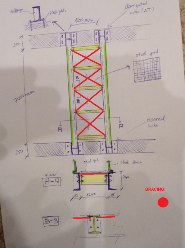
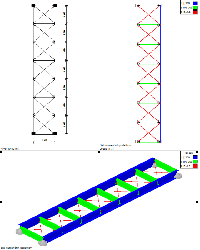
Primary steel beam is 'C' section 85/240 mm. I like using 'open' sections since they are easy to install - bolt.
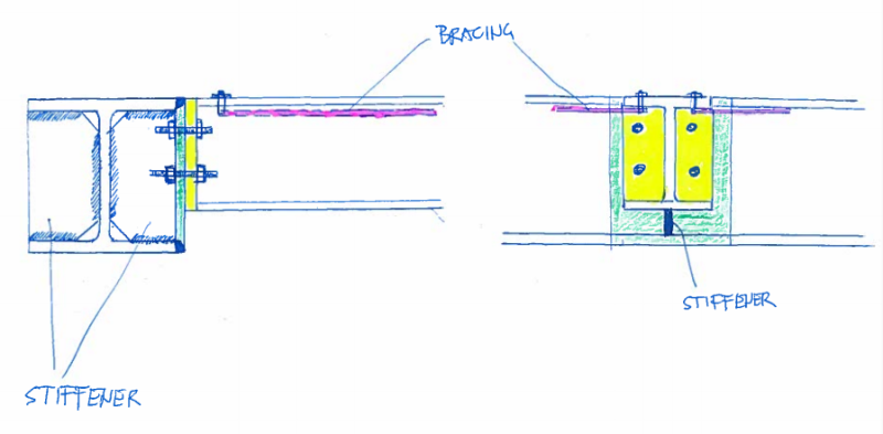
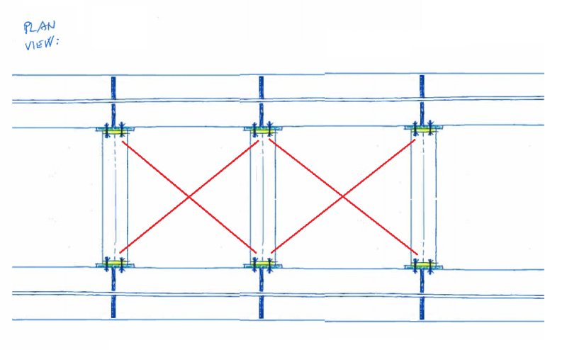
Secondary beams are bolted to the primary beams as shown below (pinned connections at both sides). I was thinking about using 'I' section since flange provides bearing seat for steel grids.
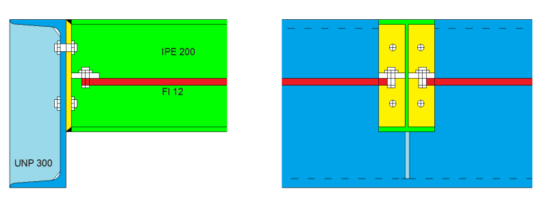
Steel fence in fixed to the flange of primary beams.
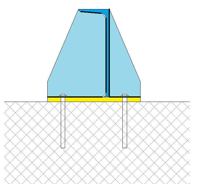
At the end of primary beam there is a steel plate that is welded to beam.
Plate is anchored to existing concrete wall bellow.
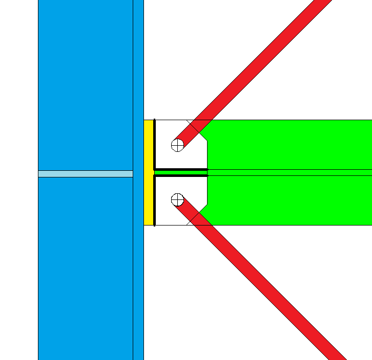
One side of beam has standard holes and other side has elongated holes because of steel temperature - expansion/shrinkage since bridge will be outside where temperature change.
What do you think about my design? Any better suggestion?
The only thing I don't like is that primary beam has pretty thin web (9,5 mm), but I think it shouldn't be a problem since forces are small. Buckling of compression flange (from bending moment) shouldn't be a problem since there are secondary beams between that provide lateral support.
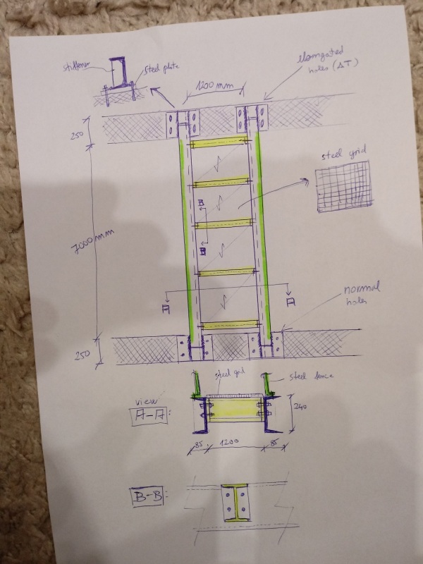
Bridge is 1,20 m wide and its span is around 7 m.
I'm wondering about my selection of steel cross sections and details.
Primary steel beam is 'C' section 85/240 mm. I like using 'open' sections since they are easy to install - bolt.
Secondary beams are bolted to the primary beams as shown below (pinned connections at both sides). I was thinking about using 'I' section since flange provides bearing seat for steel grids.
Steel fence in fixed to the flange of primary beams.
At the end of primary beam there is a steel plate that is welded to beam.
Plate is anchored to existing concrete wall bellow.
One side of beam has standard holes and other side has elongated holes because of steel temperature - expansion/shrinkage since bridge will be outside where temperature change.
What do you think about my design? Any better suggestion?
The only thing I don't like is that primary beam has pretty thin web (9,5 mm), but I think it shouldn't be a problem since forces are small. Buckling of compression flange (from bending moment) shouldn't be a problem since there are secondary beams between that provide lateral support.