Eng-Tips is the largest engineering community on the Internet

Intelligent Work Forums for Engineering Professionals

steel bridge truss top chord compression

Status
Not open for further replies.

simplebm

Structural
Apr 28, 2013
24
0
1
US
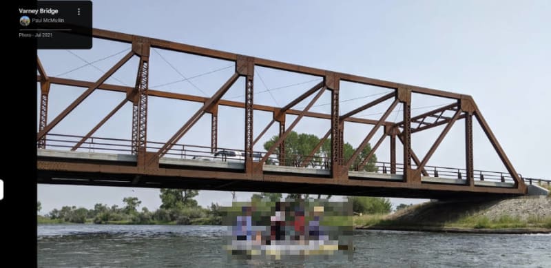
I just saw a video of a steel truss bridge erection. It was a two lane (two trusses) span of 210 feet.
The trusses were 14.67 ft deep. The floor was going to be steel beams and concrete deck.
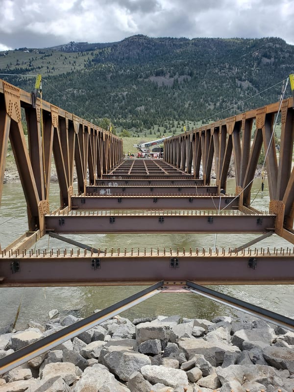
There was no horizontal bracing at the top chords of the trusses. How is the top chord designed for compression with
a span of 210 feet? Is there a reduced allowable stress based on 210 feet span? My background is buildings, not bridges.
 
Replies continue below

Recommended for you

that is a pony truss (might go by other names in other places). The top chord is braced laterally by the web members. It requires a stiff connection between the web and bottom chord/floor beam. The effectiveness of the bracing is impacted by the stiffness of the webs, floor beams, and the connections.

This is just one of the first few links I came across doing a quick google search on pony trusses:
Lots of info out there on this system if you want to read up on it more.
 
I fish here all the time! That bridge got blasted by the Yellowstone river flood in 2022. I'll have to keep an eye on the progress :)

210' sounds like quite the span for a 14' deep truss, but I don't know much about bridge design. Similar new-ish bridges in the area are much more substantial. This one is on the Madison River and spans ~100'. Appears to be about 15-20' tall and comp chords are supported. Interesting.

Perhaps there is substantial rigidity between the bridge deck stringers (?) and the truss verticals that provide a lot of rotational restraint in the out of plane direction? Similar to how smaller truss-type pedestrian bridges deal with the problem?

Snipaste_2024-08-16_12-51-41_hdyfxt.jpg
 
I am not convinced that the rigidity was evaluated. The crossbeams connect to the verticals with only two bolts above the top flanges (rest are in the web area, providing minor bending resistance and stiffness), the end-plate is thin, verticals seem to lack web stiffeners at the crossbeam flange locations (for a column moment joint, one would continue the crossbeam flange compression into a column web stiffener), and there are no triangular plate brackets (preventing joint rotation by plate in-plane stiffness) between the crossbeam top flange and the gusset plate.

Search the internet for old railway truss bridge crossbeam connections to see what a rigid pony truss (or ordinary truss) crossbeam-to-column joint should include.

The K-bracing is also oddly connected to a very small plate - typically, the bracing would connect to a plate extending to the lower chord.
 
Status
Not open for further replies.
Back
Top